Lydia Ran, Morganne Gagne, Jayson Garmizo, Gautam Meka
Duke University
ABSTRACT
The client is a young boy with sensory defensiveness, exhibiting strong negative reactions to external stimuli such as touch, sound, and taste. The best methods to calm the client are through spinning and vibration. The goal of this project was to develop a motorized spinning device that the client can safely operate independently. The design consists of a circular platform driven by a gearmotor and sprockets connected by a chain and two large vibrating buttons that power the device only when pressed down. Using this device, the client is able to calm himself independently, learn cause-effect relationships, and improve balance.
http://youtu.be/A7pBjBgDJ9A
INTRODUCTION/BACKGROUND
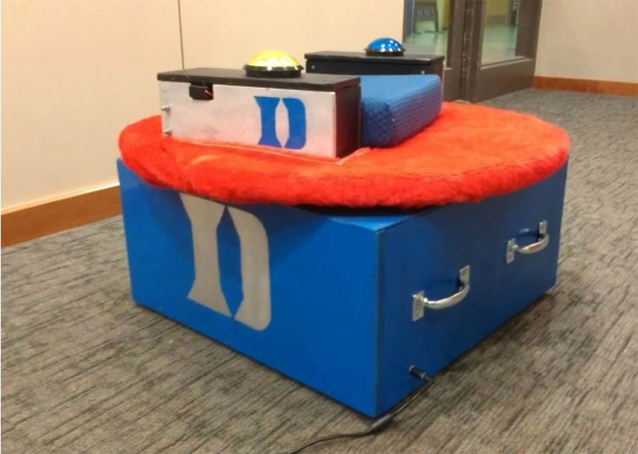 Figure 1. Spin n' Grin
 People with sensory defensiveness have a negative reaction to protective senses that are typically considered harmless and non-irritating. This often results in social and emotional problems including patterns of avoidance, sensory seeking behaviors, hyper-vigilance, anxiety, and even aggression [1]. Some calming activities include use of vibrational toys or massagers, swings, and weighted products such as blankets, lotion rubs, jumping activities, spinning, music and lights. A classic device used to calm people with sensory defensiveness is the Sit n’ Spin toy.
Our client, Pharrius, is a six year old boy with Trisomy 22, which is exhibited in his sensory defensiveness. When overstimulated, he will often bite, cry, or hit himself. Through occupational therapy, it was found that spinning, lights, and vibration calm him down. Because he has limited motor control, he cannot independently operate calming toys such as the Sit n’ Spin. Our goal was to develop a device that would incorporate these calming sensations that he could use by himself and develop his sense of cause and effect to improve his communication skills.
PROBLEM STATEMENT
The client needs a device that would provide calming stimuli, such as spinning and vibration, that he can use independently of his mother or his occupational therapist and would also incorporate educational components on cause-effect relationships. The solution needs to be safe, able to spin bidirectionally, contain vibrating feedback, be self-operable/self-accessible, be self-operable/self-accessible, and to maintain a child-friendly appearance.
DESIGN AND DEVELOPMENT
For our client to be independent, we based our device around motorizing the spinning motion. This required both mechanical components, to stabilize the user and to translate the rotation of the motor, and electrical components, to power the motor based on signals from the user.
Mechanical Components:
Motor/Wheel hub support system
 Figure 2. Motor/wheel hub system
We designed a motor/wheel hub support system, seen in Figure 2, that includes the motor, chain and sprocket system, and wheel hub. This provides the bulk of the rotational motion.
A 14 rpm 12V DC gear motor is mounted at the corner of a medium density fiberboard (MDF) base and supported by four steel S brackets and 2 aluminum diagonal braces. The four S brackets point outward to provide enough tension to the chain, while the two diagonal braces point inward to prevent jerking caused by the change in momentum when the device turns on. On top of the motor is a sprocket that is attached to a chain. The chain then extends to a larger motorcycle sprocket. This sprocket was machined to have the same inner diameter as the outer diameter of a Jeep Cherokee wheel hub. The sprocket was then welded to the outside of the wheel hub. The motion of the motor shaft turns the sprockets, which in turn spins the wheel hub. The difference in sprocket size gears down the spinning speed from 14 rpm to 8 rpm.
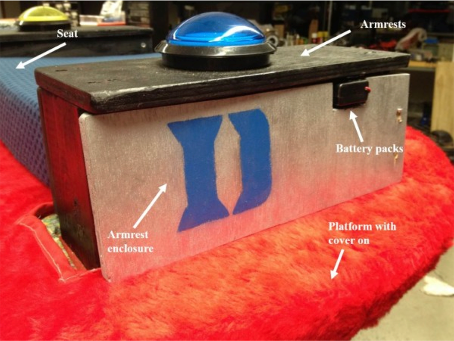 Figure 3. Platform, seat, and armrests
The wheel hub is attached to the MDF base by three groups of two wooden blocks with aluminum panels between each group of wooden block supports. The wheel hub is bolted to the middle of each aluminum panel. A 1998 Jeep Cherokee brake rotor is attached to the wheel hub to provide further support for the platform by increasing the surface area the platform rests on.
Platform, seat, and armrests
Platform, seats, and armrests, seen in Figure 3, were added to the device to provide the user with a place to sit. To do so, a circular MDF platform is attached to the brake rotor. Carpet foam is glued on to the platform to provide comfort to the user. A removable red fur fabric cover can be wrapped around the carpet foam. The red fur fabric cover and memory foam seat cushion provide decoration, texture, and support for the user.
Plywood armrests are located on either side of the platform to hold the buttons in place and allow suitable user posture. To accommodate the client’s arm length, the buttons are mounted to the armrests. AA battery packs that power the IR remote, LED button light, and the vibrational motors are attached by Velcro and located under the armrests. Electrical circuitry are hidden by a PVC pipe under the armrest, allowing the wires and circuits to run beneath the spin platform. The armrests are then enclosed by an armrest enclosure made of wood panels which can swing open to allow the user to replace batteries. The vibration motor battery pack is located in a slot within the wood panel, allowing the user to turn vibration on or off through a switch on the battery pack.
Base enclosure
Mechanical and electrical components are hidden from user reach by enclosing a MDF frame around the base. For ease of transport, rubber feet were added and two handles each are bolted onto two of the MDF panels. The 12V DC adapter that powers the motor plugs into a coaxial plug on the base enclosure.
Electrical Components:
IR wireless circuit
The large easy push buttons, located on the armrests, are each connected to an IR transmitter, which transmit unique IR codes. When the button is pressed, power is delivered to the LED inside the button and to the IR transmitter, which sends an IR code to the IR receiver. IR transmitters and circuitry are attached by Velcro directly underneath the platform. Power is supplied by a battery pack of 2 AA batteries.
Bidirectional spinning circuit
The bidirectional spinning circuit determines which button is being pressed and controls the motor spin direction. An Arduino microcontroller collects input from the IR receiver and outputs voltage to the BDX67A and NTE123 transistors, depending on which button is pressed. When pressed, both buttons turn on Arduino Pin 10, which activates the BDX67A transistor, allowing current to flow through the entire circuit. As a result, power is delivered to the motor. Only the yellow button turns on Arduino Pin 9, activating the NTE123 transistor, connected to the DPDT relay. When the relay coil is energized, both switches throw to the normally open position, reversing the polarity of the voltage delivered to the motor. By delivering -12 volts to the motor instead of +12 volts, the spin direction reverses.
EVALUATION
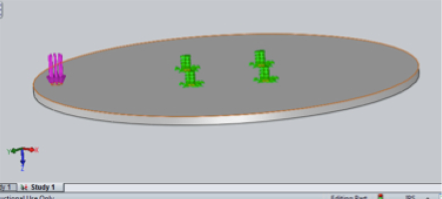 Figure 4. Solidworks model of device
The final device was evaluated to ensure safety, minimal deflection of the base spin platform to avoid interference and pinching points, ease of use for the client, and device effectiveness. A quantitative analysis was performed in which a Solidworks model of the base platform, seen in Figure 4, was created to observe theoretical deflection when different weights are applied near the edge of the device, representative of the client accessing/leaving the device as well as the relative position of the client’s center of mass during operation of the device. The Solidworks model was then verified by manually measuring platform deflection as the same weights values were placed near the edge of the surface. An average maximum deflection of about 9.44 mm was observed when nearly 70 kg were placed on the edge, a mass nearly four times that of the client.
 Figure 5. Our client using the device.
To evaluate the ease of use as well as device effectiveness, the client was allowed to operate the device to determine its difficulty level and to observe his reactions, seen in Figure 5. The client was able to quickly realize the cause-effect relationship – that pressing the button resulted in spinning of the platform. Additionally, the combination of spinning, vibration, button lights, and the tactile sensation of the fuzzy platform cover all helped to relieve the client’s symptoms in a instantaneous manner. Our client is non-communicative, but within seconds of use, the client went from the verge of tears to a state of happiness, reducing symptoms that include hitting and biting himself, yelling, crying, and grinding of the teeth.
DISCUSSION AND CONCLUSIONS
Currently, our client is acclimating himself to the device, learning which button spins in which direction and how to hold the buttons down continuously in order for the device to continually function. On our first visit to observe him operating the device, our client was easily using the device with limited help from his mother, and the effect that the spin and vibration had on diminishing his sensory discomfort was substantial. We understand there is a learning curve for our client, but can already see that the simple nature of having two buttons operating the device will allow him to learn the cause-effect relationship for each button. We also hope to see improved balance with repeated use of the device, as we purposely avoided adding a backrest to address this need.
In conclusion, the Sit n’ Grin device met the goals of the project in that the device is capable of bidirectional spinning and vibration, as needed by the client. The device met our major functional and performance specifications of:
- Being safe: As shown by our Solidworks and quantitative analysis, the weight the device can take before substantially deflecting is at least 150 lbs, which is much greater than the weight of our client now and that anticipated in the future. Analysis also demonstrated the tipping does not occur when excess weight is applied on edges. Additionally, all electrical equipment is safely enclosed and out of reach.
- Capable of bidirectional spinning: Positive and negative voltages are capable of being provided to the motor allowing two directions of spinning. It has the ability to spin at 8 rpm (deemed effective by the client’s occupational therapist and mother).
- Capable of providing vibrational feedback: Vibrational motors were added under the buttons. Client testing demonstrated that the client feels and, based on reaction, enjoys the sensation.
- Accessible/Easy to use: The device has a height less than 18 inches. From client testing, we have found the client to have little to no difficulty in getting on the device or having trouble understanding how to use the device. Within minutes, he had already started to enjoy the device.
- Self-operable: The client has only needed some help from his mother during initial use. It is expected that he will learn how to use the device completely independently.
- Maintaining a child-friendly appearance: Bright colors and textures enjoyed by the client were used.
Thus, we have succeeded in designing a device our client can use to spin independently, as well as experience other stimuli such as lights and vibration, as a mechanism to self-calm.
REFERENCES
[1]. Moore, Karen. “Learning about Sensory Defensiveness.” Sensory Defensiveness. 2006. 14. September. 2013. <http://www.sensoryconnectionprogram.com/sensory_defensiveness.pdf>
ACKNOWLEDGEMENTS
We would like to thank our clients, Tomeica and Pharrius, and Robbin Newton, our client’s occupational therapist, for their patience and guidance. Special thanks to Dr. Larry Bohs and Costi Shami for their support and insightful design suggestions, Greg Bumpass and Steve Earp for their help with mechanical components, and Matt Brown and Dr. Mark Palmeri for their advice on electrical components.
Audio Version PDF Version