A New Method for Internet-based Dynamic 3D Force Vector Visualization of Stance Phase Gait Kinetics using On-Board Sensors. Case-Study: A Right Unilateral Hemi-Pelvectomy Patient
Qili Chen1, Douglas Briggs2, Frank Fedel3, Yi Ming Zou2
Beijing Information Science & Technology University1, University of Wisconsin Milwaukee2, Eastern Michigan University3
ABSTRACT
Motion of inanimate objects, animal, or humans occurs in three spatial dimensions, but software that provides prosthetists with a dynamic 3D view of the effects of component selection and alignment is not currently available. Access to such software has the potential to enhance prosthetic management of lower limb amputees and improve their quality of life. Accordingly, said system has been developed to facilitate internet-based visualization of force vectors in three dimensions using data obtained with a 6 degree of freedom Intelligent Prosthetic Endoskeletal Component System (iPecsTM) installed in the prosthesis of a hemi-pelvectomy amputee.
The system is capable of transmitting forces and moments of strain gage (XYZ force and moments), that can update each second for up to 18 hours of continuous data collection.
This study details the results obtained with a single subject; a female physically active 27 year-old unilateral transpelvic amputee. The subject was selected for analysis because of the extreme challenge posed by the high level of amputation, and the need to demonstrate that the system developed could be effectively used to visualize in 3D dynamic force vectors calculated from the on-board device located within the knee joint up to the amputee’s pseudo hip joint.
In the United States hemi-pelvectomy amputees constitute only 0.4% of the lower limb amputee population; worldwide the percentage is much higher.
Results confirm the similarity in morphology of the force-time traces produced using the vertical force component obtained from forceplates Fz (N) and the axial force component magnitude obtained using iPecs (Faxial, N), for self-selected speed walking trials with the prosthetic leg. An analysis of 44 separate steps with the patient’s prosthetic leg yielded comparable peak force and normalized peak force values (mean difference of 25 N in favor of the mean peak ground reaction force 557N fp/532 N iPecsTM which yielded mean normalized values of 12.28 N/Kg fp and 11.728 N/Kg iPecsTM). Three-dimensional force vector visualization using iPecsTM data produced a valid and reliable dynamic 3-D force vector visualization of a unilateral hemi-pelvectomy subject walking with her conventional prosthesis that she was accustomed to using. No attempts were made to display in 3D the force vector differences in peak force magnitude and patterns of force distribution caused by changes in component selection and their alignment.
BACKGROUND
Observational gait analysis with its inherent drawbacks and inaccuracies is routinely used to assess a lower limb amputee’s ability to ambulate at the time of initial fitting and during subsequent visits that necessitate adjustments in alignment. Typically, prosthetists view the patient walking from the side (sagittal plane view), and behind and in front (frontal plane views). Gait laboratories produce 2-D vector trajectories superimposed on video of subjects walking using the same bi-planar views, but the process is time consuming, expensive, and unavailable to the majority of prosthetists. Prosthetic management of hemi-pelvectomy amputees where the transpelvic amputation is completed at the junction of the sacrum and ilium is especially challenging as is the interpretation of HP gait using observational gait analysis.The primary consideration with any transpelvic socket design is that the patient’s weight is borne against the socket wall through soft tissues alone. The socket extends to the body midline and encompasses the lower rib cage bilaterally, with the abdomen and the pelvis on the sound side. Loss of the pelvis on one side and therefore the ability to initiate forward movement and achieve axial loading, poses a significant challenge for both amputee and prosthetist. The mechanism by which the method of desirable loading occurs is facilitated by applying an upwardly directed load on the abdominal wall and on some occasions the abdominal wall and rib margin, to increase the intra-abdominal pressure, and prevent vertical movement within the socket. Once weight is accepted through the abdominal tissue the prosthetist concentrates on recreating the lost height of the resected hemi-pelvis to provide an opportunity for standing and walking. Unfortunately, HP amputees have to use atypical motions to generate appropriate forces to advance the prosthetic limb that include vaulting on the sound side, hip hiking on the prosthetic side during swing phase, and posterior tilting of the pelvis during terminal stance to initiate hip and knee flexion. Prosthetists modify the positive plaster model of the transpelvic residuum to induce a diagonally directed compressive force in the socket design to support transpelvic soft tissue and eliminate the risk of perineal shear force and tissue breakdown. A belt attached to the socket is designed to exert a diagonal force directed from the transpelvic socket toward the intact leg side to help prevent lateral shifting of the socket and minimize the shear forces exerted on the soft tissue. Three concerns need to be addressed with HP amputation when half of the pelvis is missing. Which areas are to be used for weight bearing? How can axial loading best be applied to the remaining skeletal structure to facilitate ambulation? How can the prosthesis best be stabilized in the absence of an iliac crest?
PURPOSE
The purpose of this case study was to:
- Use Matlab and commercially available software to develop a system that would permit prosthetists to visualize force vectors projected upwards from the center of the iPecsTM to the pseudo-hip joint of a hemi-pelvectomy amputee using data collected with on-board sensors.
- Verify the accuracy of data collected with the iPecsTM device by comparing it with force and moment data obtained with force plates.
METHOD
Subject
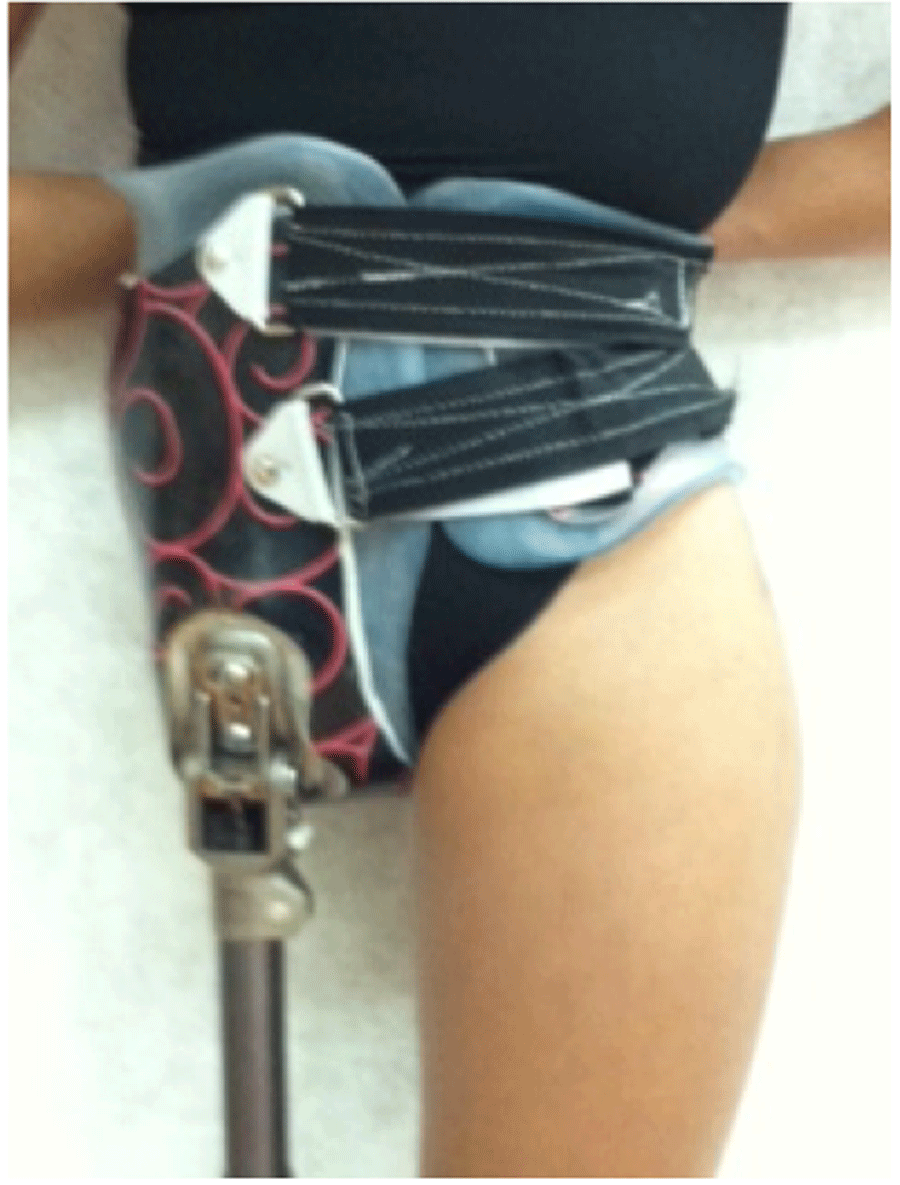
A physically active female subject age 27, 5’0” (1.524 m) tall, body mass of 100 pounds with the prosthesis on (45 kg./444.82 Nf~) volunteered for the study. IRB approval for this study was granted. An American Board Certified prosthetist statically aligned the transpelvic prosthesis. The subject’s conventional prosthesis consisted of a single axis hip joint, a programmable knee, and a multi-axial prosthetic foot with an iPecsTM unit installed proximal to the knee joint. Two bolts attached the prosthesis to the anterior surface of the transpelvic socket at a point inferior to the intact leg’s hip joint.
Instrumentation
Procedures
Weight distribution on both legs during quiet standing was determined by having the subject stand with each foot positioned on a separate force plate and recording the ground reaction and iPecsTM forces. The subject completed 11 walking trials at self-selected speed over two force plates installed in a 15 meter walkway.
Two-dimensional force vector plots
 Figure 1: Sagittal Plane 3-D Force Vector View
The vertical distance (m. offset) needed to produce the 2D sagittal plane(YZ) and frontal (XZ) vector plots and the 3D plots was calculated from the eight shear and axial force strain gages located in the center of the iPecsTM up to the top bolt attachment that constituted the pseudo-hip joint
Software Development
The original program to create moving displays of 3D force vectors from data obtained using iPecsTM was written using Matlab. Commercially available software was subsequently used to permit internet-based dynamic visualization of the 3D vectors.
The client of the application was developed using HTML5, the language used to structure and present content on the World Wide Web. PHP was used for web development. User control of browsers was facilitated using JavaScript, and a JavaScript 3D library was also used. MySQL was used for database management.
Rendering interactive 3D graphics within a compatible browser without the use of plug-ins was achieved using WebGL.
Upload raw data from the i-Pecs to the web database online. |
| ⇓ |
Normalize the raw data in the web server of the application. |
| ⇓ |
Calculate the coordinates for the display. |
| ⇓ |
Send necessary information to the browser and display 3D representation using WebGL. |
RESULTS
Similarities in the magnitude and direction of three-dimensional force vectors and patterns of force distribution (impulse) projected from the prosthetic knee up to the pseudo-hip joint of a physically active unilateral amputee walking at self- selected speed, was observed based on comparisons of force plate with iPecsTM data. The results of this study demonstrated:
- Minor differences were observed between the peak forces and their normalized equivalents in favor of the ground reaction forces (mean 2% difference);
- Smaller mean differences were observed between the patterns of force distribution (N-s impulse) recorded with both devices (mean difference of 1.45% in favor of the ground reaction force impulse);
- Analysis of the center of pressure estimates for the intact and prosthetic legs using force plate and iPecsTM data confirmed that although instability of the prosthetic leg occurred during the single support stance phase of gait, the prosthetist’s dynamic alignment induced the desired narrow gait (mean 81mm/3.19 inches separation) between pre-swing of the intact leg and the ensuing initial contact of the prosthetic leg during initiation of the double support phase for all 44 walking steps recorded with each leg. The ensuing transition from double support phase to single support phase on the prosthetic leg was relatively unstable compared with the equivalent COP trace exhibited by the intact leg.
DISCUSSION
This work represents the initial stage in the development of internet-based 3D force vector visualization of amputee activities using Matlab and commercially available software and prosthesis integrated sensor data.
Given the multitude of anatomical, biological and mechanical factors that influence prosthetic fitting, alignment, and long-term management of lower limb amputees, internet-based dynamic 3D force vector visualization has the potential to help prosthetists quantify and visually assess the true effects of changes made in component selection, and static and dynamic alignment on amputee mobility. It will assist them improve amputee function, document outcomes, and validate clinical practice. Linked with high-speed video and animated images of the prosthetic socket the system developed will serve as an invaluable adjunct to the inadequacies of observational gait analysis currently used by prosthetists.
Study Limitations
The results obtained are confined to a case study. Further work is required to apply the 3D force vector visualization technique used in this study for assessment of below and above-knee amputees who constitute the majority of the lower limb amputee population. The addition of a tri-axial accelerometer, 3D rate gyroscope and a magnetometer to the iPecsTM device is planned that will greatly enhance the realistic and accurate portrayal of 3D dynamic force vector displays. Although changes in the self-selected speed of walking by lower limb amputees affect the load deformation curves and thus the roll-over characteristics of various prosthetic feet, that in turn influence the 3D force vector magnitudes and impulse characteristics transmitted upwards from the base of the socket to the point of interest on the surface of the socket or to a specific joint, the dynamic 3D force vector displays produced by the system are informative and reflect the current state-of-the-art technology.
The long-term goal is to create prosthetic socket models for the various levels of lower limb amputation and superimpose the dynamic 3D force vector displays on them. Models include patellar tendon bearing (PTB) and total surface bearing (TSB) sockets for below-knee amputees, sub-ischial, ischial containment and MAS sockets for above-knee amputees, and transpelvic sockets for hemi-pelvectomy amputees. Once developed the models can be linked with a commercially available electronic test socket manufacturing software that will provide a more realistic portrayal of the dynamic animated 3D force vectors transmitted upwards through the prosthetic socket during various gait activities. Work continues to improve the accuracy of the center of pressure estimate derived from the iPecsTM force and moment data, using pitch, yaw, and roll algorithms employed in the aircraft industry.
CONCLUSION
The results of this study has clinical implications for lower limb amputees. For the very first time prosthetists will be able to view in slow-motion the effects of changes that they make in component selection and subtle adjustments in static and dynamic alignment, on amputee mobility. Changes in both the magnitude of peak forces and the pattern of force distribution occurring within a prosthetic socket or transmitted up to the pseudo hip joint of a hemi-pelvectomy amputee, can be quantified and visualized in three dimensions. The system of internet-based visualization of dynamic 3D amputee indoor and outdoor activities using on-board sesnsors has potential to help prosthetists assist amputees ambulate and perform the more intimidating activities of daily living that include negotiating ramps and stairs, and raising and lowering themselves from a chair, a toilet seat, or couch. Further research is needed to refine the technique presented for the various levels of lower limb amputation.
REFERENCES
Beck, LA., Einertson, MJ., Winemiller, MH., et al. (2008). External hemipelvectomy limb amputation with partial ilium & pubic preservation. Journal of the American Physical Therapy Association. Vol 88, no. 8, 916-927.
Briggs, DW., Fedel, FJ., Harrington, R., & Krapf, C. (2009). Alpha and Beta Testing of a Wireless 6 DOF Prosthetic Pylon Sensor. Unpublished.
Fiedler,G., Slavens, B., Hafner B.J., Briggs,D.,& Hafner, B.J. (2014). Criterion & Construct Validity of Prosthesis-Integrated Measurement of Joint Moment Data in Persons with Trans-tibial Amputation. Journal of Applied Biomechanics. *In press.
Kambhampati, SBS (2007). Constructing a Pedotti diagram using excel charts. Journal of Biomechanics vol.40, 3748-3750
Kannenberg, A., Ludwigs, E., & Wustefeld, D. (2014). Function and walking capabilities of hip disarticulation amputees with the Helix 3-D prosthetic hip joint. Thranhardt Lecture, American Academy of Orthotists & Prosthetists, 40th Academy Annual Meeting & Scientific Symposium.
Koehler S.R, Dhaher Y.Y, & Hansen, A.H. (2014). Cross-validation of a portable, six-degree-of-freedom load cell for use in lower limb prosthetics research. Journal of Biomechanics 47,1542-1547.
Papaioannou, G; Mitrogiannis, C; Tsiokos, D; Fiedler, G; & Leydet, M. (2011). A New Wireless Gait Laboratory Device for Lower Extremity Prosthetic Kinetic Assessment.
ACKNOWLEDGEMENTS
The authors would like to thank Eastern Michigan University for use of its gait laboratory, Timothy R. Lindsay its director for data collection, and Rodney Coleman an American Board Certified Prosthetist for Wright & Filippis Flint, Michigan, who aligned the prosthesis and continues to be responsible for the long-term care of the volunteer hemi-pelvectomy amputee tested in this study.