A PORTABLE, LOW-COST WHEELCHAIR ERGOMETER DESIGN BASED ON A MATHEMATICAL MODEL OF PEDIATRIC WHEELCHAIR DYNAMICS
Jacob R. Rammer MS, Susan A. Riedel SM PE, and Gerald F. Harris PhD PE
Orthopaedic and Rehabilitation Engineering Center, Marquette University dept. of Biomedical Engineering and Medical College of Wisconsin dept. of Orthopaedic Surgery, Milwaukee, WI
ABSTRACT
Evaluation and training of wheelchair propulsion improves efficiency and prevents orthopaedic injury in pediatric manual wheelchair users. Ergometers allow static propulsion and emulate typical conditions. Currently available ergometers have deficiencies that limit their use in motion analysis. A new ergometer is developed and evaluated based on a model of wheelchair inertial dynamics that eliminates these deficiencies. This makes integrated motion analysis of wheelchair propulsion in current community, home, and international outreach efforts possible.
BACKGROUND
Pediatric manual wheelchair users (MWU) include children with cerebral palsy and other orthopaedic disorders, including traumatic spinal cord injury. MWU, especially when inexperienced, have increased risk of upper extremity (UE) orthopaedic injuries, particularly to the wrist, shoulder, and rotator cuff [Mercer et al.]. Research identified common functional approaches to propulsion, differentiated by sagittal hand position relative to the handrim during the recovery phase [Boninger et al.]. These approaches have differences in kinematics observed at each of the UE joints and in the muscle activity patterns that produce the motion. Therapists typically train MWU in a patient-specific propulsion methodology focused on reducing risk of biomechanical injury and increasing efficiency in everyday mobility.
Functional Assessment and Telerehabilitation
Laboratory-based motion capture technology has been combined with UE musculoskeletal models to evaluate orthopaedic behavior during wheelchair propulsion [Schnorenberg et al.]. Recent work has applied low-cost markerless motion analysis and similar UE musculoskeletal models to allow detailed kinematic assessment outside the laboratory, with a specific focus on community and home applications [Rammer et al.]. In either method, a wheelchair ergometer is typically employed to allow static positioning of the MWU while simulating actual propulsion.
The recent development of markerless, low-cost motion analysis enables visual biofeedback to be employed as a training tool, providing instruction and training to users. A primary requirement for successful implementation and practicality of such a system is an effective ergometer design.
Wheelchair Ergometers
Wheelchair ergometers provide a platform on which the wheelchair may be propelled by users in a static position while simulating the resistance of normal mobility. Systems typically use rollers connected to a rotating mass designed to provide inertial resistance. Practical application of these devices as a component of motion analysis techniques has identified a set of deficiencies in currently available systems:
- Use of highly polished, reflective materials causes interference with imaging systems that rely on reflection of infrared light.
- Size and weight of the ergometer causes issues in transporting it as part of an otherwise compact motion analysis system to home, community, and international settings.
- In ergometers that use long continuous rollers, lateral position is not constrained and the wheelchair has a tendency to drift laterally during aggressive or unbalanced propulsion, causing inconsistency in detected position, and potential for safety risks.
- Ergometers typically have multiple resistance settings, but it is unclear how these settings relate mathematically to the MWU anthropometry and wheelchair specifications. This is relevant when the objective of a clinical tool or research study is to approximate actual wheeled mobility conditions.
- The cost of commercially available ergometers is prohibitive for outreach or home use. In the case of a low-cost markerless kinematic system, ergometer cost exceeds the cost of all other components.
PURPOSE
The purpose of this work was to improve evaluation of wheelchair propulsion and train users outside a clinical setting through:
- Identifying and evaluating all factors that influence the inertial dynamics of wheelchair mobility;
- Developing a mathematical model of wheelchair propulsion dynamics to translate typical wheelchair activity to a wheelchair propelled on a static ergometer;
- Designing, optimizing, and fabricating a novel wheelchair ergometer based on the model; and
- Evaluating the design for use in clinic, community, or home settings.
METHODS
Design Requirements
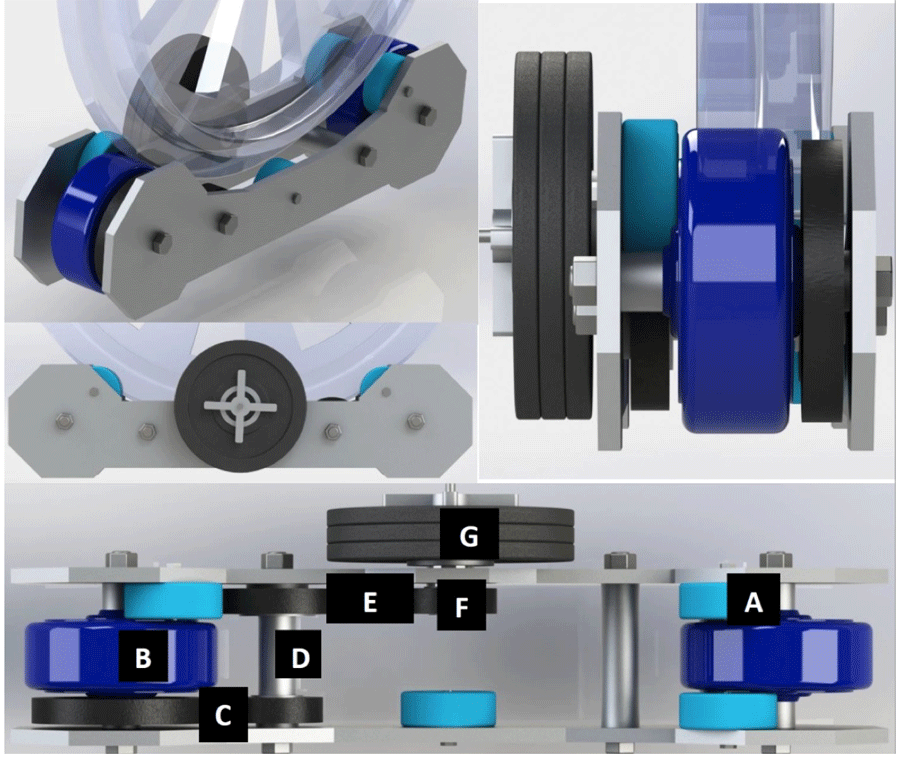 Figure 1: CAD Roller Unit Design: Support wheels (A) guide lateral motion; Drive wheel (B) actuates 2.2:1 chain drive (C); Drive shaft (D) actuates 1.6:1 chain drive (E); Shaft (F) contains rotary and lateral bearings to support attachment of multiple 2.5-lb plates (G).
Conceptual Design
The proposed ergometer (Fig. 1) consists of two separate roller units, each having two large drive wheels and smaller lateral support wheels, and two front wheel support stands. The rotating inertial resistance unit consists of a set of 2.5-lb standard barbell plates, driven by a roller chain setup.
Analysis of Pediatric Wheelchair Mobility
 Figure 2: Model – Standard (L) vs. Ergometer (R) Propulsion
Mathematical Model Development
For the initial application, simplifying assumptions are made. Internal friction and inertia of the wheelchair are considered to be minimal, and similar in either actual propulsion or ergometer cases. Friction and contact patches between the wheelchair drive wheel tire and ground are assumed to be the same and friction between the front wheels and the ground is neglected. Any effect of friction due to wind resistance during propulsion is presumed to be insignificant. A level propulsion surface and constant gravity are assumed, ignoring potential energy due to change in elevation.
An initial model (Fig. 2) is proposed based on the law of conservation of kinetic energy. The sum of the linear kinetic energy components (Eq. 1) of normal wheelchair propulsion is equated to the sum of rotational kinetic energy components (Eq. 2) of ergometer propulsion (Eq. 3).
| (1) | |
| (2) | |
| (3) |
| (4) | |
| (5) | |
| (6) | |
| (7) |
Roller units consist of multiple internal components that produce rotational inertia. Since appropriate ball, roller, and thrust bearings are specified throughout, friction of internal components is ignored. Drive components, including wheels (rubber on aluminum hub), sprockets and roller chain (steel), drive shafts (Al), and weight plates (cast iron) each have angular velocities dependent on their location in the drivetrain (Eqs. 4-7 below) and mass moments of inertia calculated using models produced in CAD software.
Combining all terms and simplifying (Eq. 8) results in a model describing the wheelchair and subject mass simulated by the ergometer based on the components, number of weight plates attached, wheelchair size, and subject anthropometry.
(8)
The model is implemented as a MATLAB function, allowing analysis with varying inputs. The function was used to refine the mechanical design of the ergometer and to create standardized guidelines for configuring the ergometer based on wheelchair wheel diameter and subject mass.
Final Mechanical Design, Fabrication, and Evaluation
The ergometer system was fabricated using standard hand and manual machine tools. The side panels were cut from bar stock using a metal cutting band saw, and holes drilled in appropriate locations. Drive shafts and plate attachment systems were machined on a metal lathe and vertical mill, and sprockets attached using drift pins. All parts were ground and sharp edges filleted. Finally, the system was assembled according to the design and tested for function.
 Figure 3: Weight Ranges for Applied Plates
RESULTS
Mathematical Model Results
The model produced weight ranges simulated by the ergometer based on the application of 1, 2, or 3 weight plates to both roller units. This linear relationship between user weight and required inertia is demonstrated in Fig. 3.
| WD (in) | WD (cm) | WT (lb) | WT (kg) | # PL (ea) |
|---|---|---|---|---|
| 20 | 50.8 | 13-64 | 5-29 | 1 |
| 65-115 | 30-52 | 2 | ||
| 116-167 | 53-76 | 3 | ||
| 22 | 55.9 | 20-82 | 9-37 | 1 |
| 83-144 | 38-65 | 2 | ||
| 145-207 | 66-94 | 3 | ||
| 24 | 61.0 | 28-102 | 12-46 | 1 |
| 103-176 | 47-80 | 2 | ||
| 177-250 | 81-114 | 3 | ||
| 26 | 66.0 | 37-123 | 16-55 | 1 |
| 124-210 | 56-95 | 2 | ||
| 211-296 | 96-135 | 3 | ||
| Note: WD = wheelchair wheel/tire diameter; WT = subject weight; #PL = number of weight plates attached to each roller unit |
||||
To assist in clinical application of the ergometer, the results of the above simulations may be distilled into weight ranges for given system configurations, shown in Table 1. The table is read left to right, first selecting the wheel diameter, then the range containing user weight, and applying the indicated number of weight plates to each roller unit.
Fabrication Process and Completed Ergometer
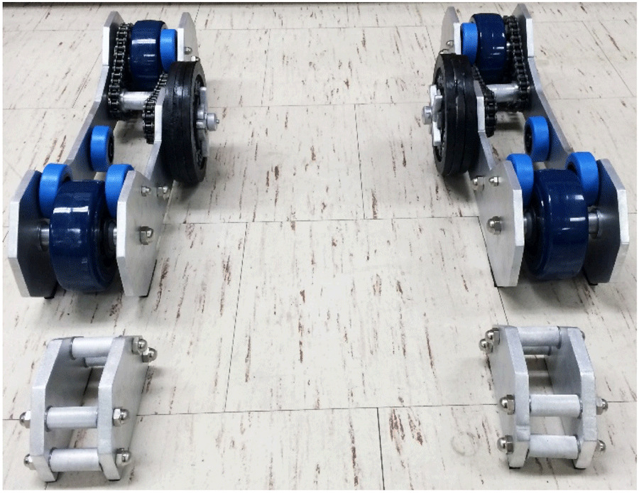
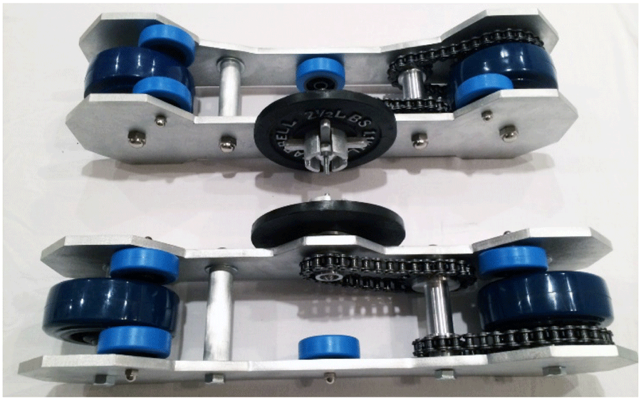 Figure 4: Assembled Ergometer System
Initial Evaluation Results
Five wheelchairs of varying sizes and designs were tested with the system (Fig. 5) to ensure broad compatibility. Markerless motion capture was used to record upper extremity motion, and test the system for compatibility with infrared depth imaging with a 24”, sport-style wheelchair. No image artifacts were observed, and the system provided a successful base for wheelchair propulsion evaluation.
DISCUSSION
Motion analysis systems provide detailed evaluation of functional behavior during actual tasks. In the case of gait, these systems are able to accommodate a full gait cycle and produce valid results. Since wheelchair propulsion is a cyclic motion with greater inertial dependence than gait, a longer distance is required for full evaluation of steady-state motion, which most motion analysis labs and home or community settings do not have. Therefore, ergometers can be used to simulate propulsion over longer distances in confined areas.
Many of the current roller systems on the market appear to focus on resistance or endurance exercise rather than accurate simulation of propulsion. Additionally, the devices have deficiencies in size, weight, cost, materials, and lack lateral stability. These issues needed to be resolved prior to the proposed use of motion analysis technology in home, community, and remote outreach settings.
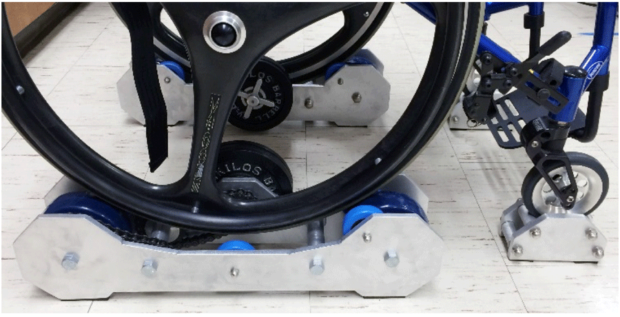 Figure 5: Ergometer with Wheelchair (24” Wheel)
| System | Weight (lb) | Size (in) | Cost ($) |
|---|---|---|---|
| McLain Roller System | ~60 lb | 40”x66”x7” | $900-1000 retail |
| New Ergometer | ~ 35 lb | (2) 5”x5”x22” & (2) 4”x4”x6” | $375 for parts/etc. |
Study Limitations
The present study developed a dynamic model, and evaluated the ergometer subject to simplifying assumptions, but did not validate the inertial dynamics of the system. Further validation is suggested before relying on the accuracy of the model. Testing of the device was limited to a pilot evaluation. A more complete evaluation with MWU is suggested. The ergometer design is limited to using 2.5 pound weight plates, producing broad weight intervals. In the future, 1.25 pound plates are suggested to allow finer adjustment.
Clinical Applications
The ergometer system will be used with markerless upper extremity motion analysis systems to detect wheelchair propulsion. The overall system, including the motion analysis technology and ergometer, is a compact, portable, cost-effective means to detect detailed UE kinematics. Directed training software using real-time visual biofeedback to promote propulsion patterns with maximum efficiency and minimum injury risk will be used to analyze and train wheelchair users in a community therapy setting (through collaboration with a camp for children with physical disabilities), and in international outreach clinics. Further development will create a home training platform with remote therapist contact.
CONCLUSION
The purpose of the present study was to improve our ability to evaluate and train manual wheelchair users in a variety of environments by developing a new wheelchair ergometer. The resulting device and an associated dynamic model provide improved compatibility with motion analysis cameras, lateral stability, and configurability based on user anthropometry and wheelchair specifications. In addition, the size, weight, and cost of the device are significantly less than currently available commercial products. Results indicate that the device is appropriate for use in remote, underserved, or home settings. Future work is suggested to employ smaller weight plates, evaluate the inertial dynamics of the device using mechanical testing equipment, and perform a thorough validation of the safety of the device prior to clinical use.
REFERENCES
Boninger M, Souza A, Cooper R, Fitzgerald S, Koontz A, Fay B. (2002). Propulsion Patterns and Pushrim Biomechanics in Manual Wheelchair Propulsion. Arch Phys Med Rehabil, 83, 718-723.
Mercer J, Boninger M, Koontz A, Ren D, Dyson-Hudson T, Cooper R. (2006). Shoulder joint kinetics and pathology in manual wheelchair users. Clinical Biomechanics, 21, 781-789.
Rammer J, Slavens B, Krzak J, Riedel S, Harris G (2015). Evaluation of Manual Wheelchair Mobility with Markerless Kinematics and Subject-Specific Musculoskeletal Modeling. Proc. 20th Ann. Mtg. Gait and Clinical Movement Analysis Society, In press.
Schnorenberg A, Slavens B, Wang M, Vogel L, Smith P, Harris G. (2013). Biomechanical model for evaluation of pediatric upper extremity joint dynamics during wheelchair mobility. J. of Biomechanics, 47, 269-76.