Vibration type hearing aid system for unilateral deafness patients
Katsutoshi Oe, Masahito Iwae, Kohji Kariya
Department of Mechanical Systems Engineering, Daiichi Institute of Technology, Kishirima, JAPAN
Introduction
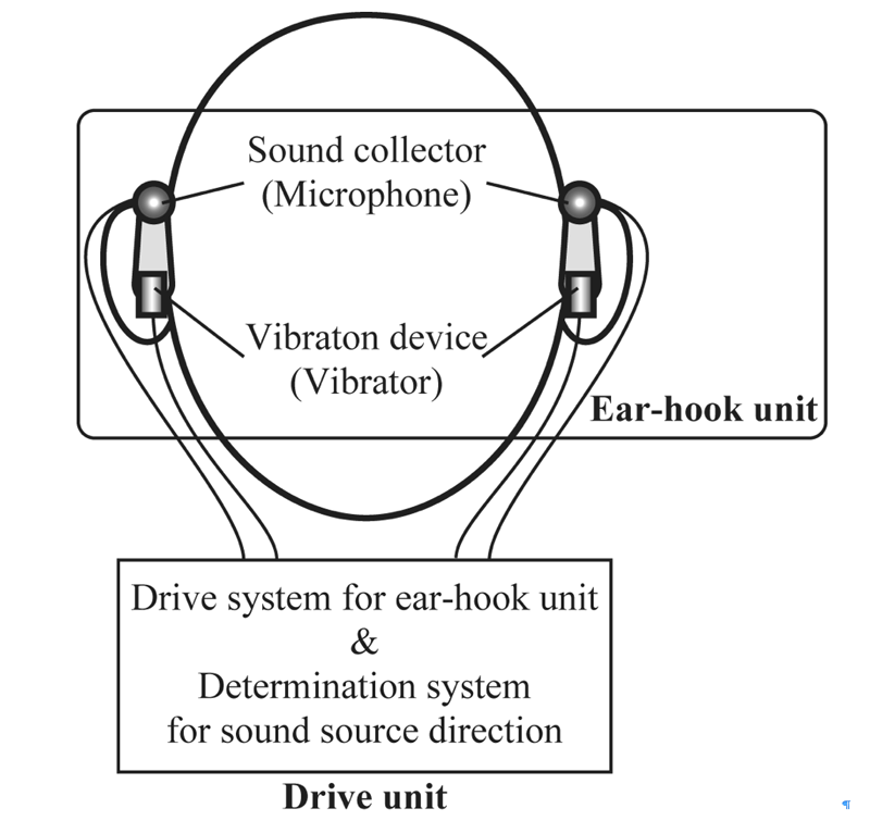
Figure 1: Schematic diagram of the proposed hearing aid system for unilateral deafness patients.
The unilateral deafness patients can’t hear other people’s voice, alarm and the other sounds by their odd ear. The human beings identify the sound direction by their both ears. Therefore, the patients who lost the hearing function of their odd ear, can not decide the direction of the sound. As the result, they can’t identify the person who speaks to them and the object that sounds the alarm. In our daily living, the direction of sound is very important information. For example, the sound of klaxon is the dangerous signal to avoid the traffic accident, and the identification of the person who spoke is very important for smooth communication. If the hearing loss is caused by conduction deafness, they can treat by using of the auditory prosthesis. However, if the cause of the handicap is sensory deafness, the conventional prosthesis has no effectiveness for them.
Figure 2: Schematic diagram of the proposed ear-hook unit.
From the above-mentioned reasons, the realization of the medical/welfare devices for the sensory unilateral deafness patients is desired. In this research, we aim to develop the new type hearing aid system with the function of sound direction indicator. To develop this hearing aid system, one of the most important things is “How to present the sound direction”. We proposed to use the vibrator as the presenter, and this system is composed a drive unit and two ear-hook unit with microphone and vibrator. In this report, we describe the following items: basic principle of new type hearing aid system, proposal of construction for ear-hook unit, circuit design for drive unit and prototypes of both units.
proposal of new type hearing aid system
Perceptive unilateral deafness
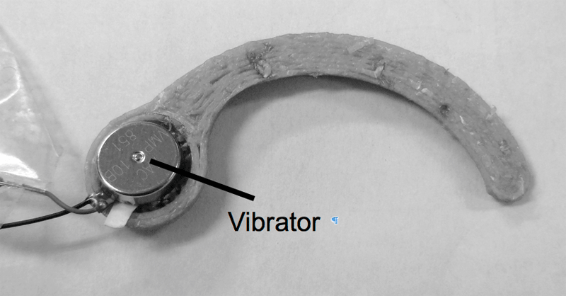
Figure 3: Photo image of the prototype ear-hook unit without microphone.
The patients who lost hearing function of one ear, lost their functions of sound direction determination. As the result, they could not identify a speaker direction, and they had problems for the communications. In addition, their abilities of danger perception were decreased. If the cause of deafness is sensory, the conventional hearing aids don’t have enough effectiveness to resolve these problems. For these patients, “cross hearing aid” is available. This device transmits the sound collected at hearing loss side to the normal side, the users can not determine the sound direction. Therefore, the new type hearing aid with the function of sound direction determination.
Concept of new type hearing aid system
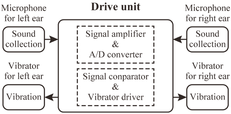
Figure 4: Schematic diagram of circuit structure of drive unit.
For perceptive unilateral deafness patients, one of the most important things is “where does this sound come from?” The concept of our new hearing aid system is the sound direction presenter. For development of this device, how to present the sound direction is the most important terms. The auditory sense is the passive sensor, then we chose the tactile sense that is a passive sensor, too. Therefore, in our system, the information of sound direction is shown by vibration. The schematic diagram of our hearing aid system is shown in figure 1.
The system is mainly consisted of 2 parts: 1) ear-hook unit and 2) control unit. The ear-hook unit is symmetrical pair for right and left ears. A compact microphone (for sound collect) and a compact vibrator(for showing the sound direction) are built into each ear-hook unit. The drive system for the microphone and the vibrator, and the determination system of sound direction are built into the drive unit. This system operates as follows:
Measurement of the sound by the microphone.
Determination of sound direction by the sound direction determination system.
Presentation of the sound direction by the vibrator.
Designing and trial production of new type hearing aid system
Ear-hook unit
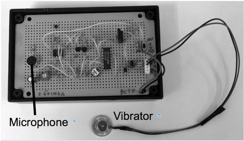
Figure 5 shows the prototype drive unit. This unit could drive the vibrator by the detected sound.
We designed the ear-hook unit as shown in figure 2. This unit includes a compact microphone and a micro vibrator inside of its body. This unit was designed aiming at the good feeling of ear hooking.
We made a prototype ear-hook unit to estimate the feeling of ear hooking. Figure 3 shows the prototype unit. This unit was produced for estimation of the feeling, and it didn’t have a microphone. It was confirmed that this unit had good feeling.
Drive unit
Figure 4 shows the schematic diagram of the circuit structure of the drive unit. The drive unit is connected to the microphones and the vibrators of both side by wires, and it consists of the circuit of signal amplifier and A/D converter, and the circuit of signal comparator and vibrator driver.
The functions of this unit is as follows:
1) Power on/off, reset.
2) Mode changer of measurement/calibration.
3) Adjuster of sound signal sensitivity.
4) Adjuster of vibration level.
5) Delay time of vibrator adjuster.
conclusion
In this report, we proposed the new type hearing aid system for the perceptive unilateral deafness patients, and designed the device and product experimentally. In the future, the operation experiment, the evaluation of its performance and the improvement of the devices will be performed.
References
Harford, E., & Dodds, E. (1966). The clinical applications of CROS-A hearing aid for unilateral deafness-. Arch Otolaryngol, 83, 5, pp455-464.
Acknowledgements
A part of this research is performed by the “Research & Development Grant of Daiichi Institute of Technology (2014 and 2015)”.