Development and Simulation of a Self-Leveling Algorithm for the
Mobility Enhancement Robotic Wheelchair
S Andrea Sundaram, Jorge Candiotti, Hongwu Wang, and Rory Cooper
Department of Rehabilitation Science and Technology, University of Pittsburgh, Pittsburgh, PA
Human Engineering Research Laboratories, U.S. Department of Veterans Affairs, Pittsburgh, PA
ABSTRACT
This paper describes an algorithm for keeping the seat level over slopes that a wheelchair may encounter. The algorithm controls the motion of four independently movable wheels with pneumatic actuators and pivoting linkages to maintain the frame within pitch and roll limits. Simulations show positive results overall, but introducing time delays or errors in the pneumatic positions – as might be expected from a mechanical system – cause the frame angle to exceed the specified limits. Additionally, movement of the wheels is not symmetric under all circumstances. Future work will include testing the algorithm on a physical prototype, and refinement based on both the simulation and physical test results.
BACKGROUND
There are an estimated 3.6 million wheelchair users in the United States (Brault, 2012). Of these, 15% could be expected to use electric powered wheelchairs (EPW) (Cooper, Cooper, & Boninger, 2008). With the aging of the US population, these numbers are expected to grow. EPWs provide community integration, independence, and increased quality of life for persons with disabilities (Edwards & Mccluskey, 2010). Still, EPW users confront challenges when going outdoors including slopes, steps, uneven surfaces, and other environmental barriers (Ding & Cooper, 2005; Ståhle, Brandt, & Iwarsson, 2004). In the US, EPWs are typically purchased by Medicare, Medicaid, private insurance, the Veterans Administration, or State offices of vocational rehabilitation (Buning, Schmeler, & Crane, 2006). Payment guidelines often restrict justification for device functionality to that which is needed in the home. A result of this restriction is that typical EPWs give poor performance on inclines and cross slopes, do not provide sufficient traction on slippery surfaces, and are incapable of surmounting obstacles higher than 3 inches – e.g. curbs (Daveler et al., 2015). EPW users may adapt their driving behavior in order to avoid such obstacles (Daveler et al., 2015; Ståhle et al., 2004), but such compromises may prevent people from visiting the places they might otherwise choose to go.
Besides limiting independence, environmental barriers can lead to injuries for EPW users. Data from 2003 found that there were over 100,000 emergency room visits resulting from wheelchair accidents – 65% of which could be attributed to tips and falls (Xiang, Chany, & Smith, 2006). A survey to characterize wheelchair incidents found that 42% could be considered as tips and falls, and that hospitalizations were weighted toward those categories (Gaal, Rebholtz, Hotchkiss, & Pfaelzer, 1997). The same survey found that 79% of tips and falls occurred on rough ground or non-level surfaces. A study to categorize wheelchair incidents found that, of 95 respondents, 55% had experienced at least one incident in the previous three years, and 88% of those incidents were tips and falls (Chen et al., 2011).
In order to promote safety and independence for EPW users when they travel outside the home, the Mobility Enhancement Robotic Wheelchair (MEBot) was developed. Its specific functions of self-leveling when traversing inclines and cross slopes, curb climbing, and traction control were chosen based on input from focus groups conducted with EPW users, who identified ramps, curbs, and uneven and soft surfaces as their greatest obstacles (Daveler et al., 2015).
In a previous version of the MEBot, the self-leveling algorithm multiplied a rotation matrix with pitch and roll angles by a matrix containing the initial wheel positions in order to determine the new desired wheel positions to keep the frame level (Candiotti et al., 2016). A redesign of the pneumatic system and wheel linkages to increase the maximum vertical wheel travel required a more complete consideration of the linkage motion’s geometry.
GEOMETRIC MODEL
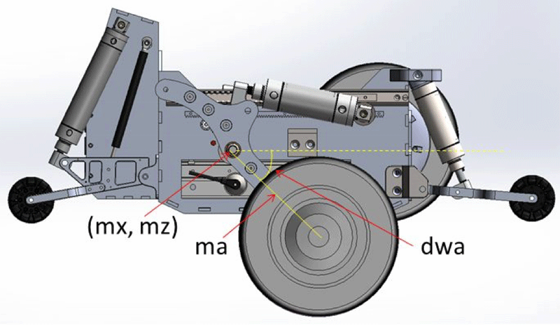
In order to know the wheel position from the displacement of the pneumatic actuator, a geometric model of each wheel’s mechanical system was created. For both the driving wheels and the rear casters, movement of the pneumatic actuator can be seen to vary the angle of the arm on which each wheel is mounted relative to a reference line on the wheelchair frame.
The angle between the drive wheel arm and a line extending horizontally from the point around which the arm pivots, dwa, can be calculated from the displacement of the actuator through a series of trigonometric relations. The position at which the drive wheel contacts the ground (dwx, dwz), relative to the main pivot point (mx, mz), with ma being the length of the drive wheel arm, is given simply by
The position of the rear caster can be related to the stroke of its actuator by similar means.
algorithm description
Determining Pneumatic Positions
When self-leveling is initialized, all four actuators – front left, front right, rear left, and rear right – are set to the midpoint of the wheelchair’s ground clearance. As the minimum and maximum ground clearances are not the same for the drive wheels and rear casters, the midpoint is calculated from the greater of the minima and the lesser of the maxima. This ground clearance is defined as 0 on the z-axis for the self-leveling algorithm.
The positions of the wheels in the x-axis can be calculated, and the 0 is defined as the midpoint between the drive wheels and the rear casters at this middle ground clearance. The positions of the wheels in the y-axis do not change with pneumatic position, and the zero position along this axis corresponds to the midline of the wheelchair.
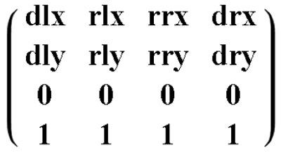
A matrix, currentM, gives the coordinates of each wheel in the, above described, coordinate system. For compatibility with the transformation matrix, the currentM matrix must be expanded to 4 x 4, with the last row being occupied by ones
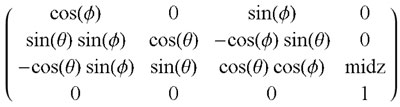
A transformation matrix takes inputs for pitch φ (phi), and roll θ (theta), measured from the IMU sensor, to perform a rotation on the current wheel positions. The transformation matrix also performs a translation to refer the new wheel positions to the bottom of the frame – a subtraction of the midpoint ground clearance midz.
The product of the rotation matrix and currentM gives the desired wheel positions to maintain the frame level. The Z-values, the vertical position of each wheel relative to the bottom of the frame, are then fed into linearized equations to obtain the corresponding displacement of each actuator. These positions are then propagated to the lower level control system to move the pneumatic actuators.
Calculating Current Wheel Positions
Based on the current position of each actuator, and the geometric model, the actual position of each wheel can be calculated in the X, Y, and Z axes. The pitch and roll angles of the plane determined by any three wheels of the MEBot can be calculated by taking the cross product of the vectors from any one of those wheels to the other two – e.g. the cross product of the vector from the rear left caster to the front right drive wheel with the vector from the rear left caster to the front left drive wheel.
The current positions from the geometric model are also used to update the wheel position matrix, currentM. However, the midpoint ground clearance must be added to each wheels’ Z-values to translate them back into the original coordinate system.
When the wheelchair seat reaches the desired position, the IMU sensor will read zero in both the pitch and roll directions. Any deviation from levelness – whether due to error in the linearization of the model, error introduced by the transformation matrix not accounting for the movement of the wheels in the X-direction, or a change in the slope encountered by the wheelchair – will cause the IMU sensor to register a nonzero value. If this value is greater than the threshold the self-leveling algorithm will iterate until both pitch and roll are below their respective thresholds. Because the wheel position matrix, currentM, includes the changes in the X-position of the wheels resulting from the geometry of the mechanical linkage, these X-direction changes – not otherwise accounted for – will not affect self-leveling performance over slowly changing angles.
Simulation results
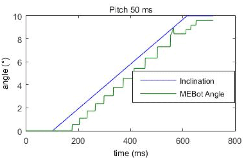
The preceding algorithm was implemented in MATLAB (The MathWorks, Natick, MA), and simulations were run in order to test its effectiveness. For each simulation, an example terrain was translated into time varying pitch and roll values relative to the horizontal. Since the pitch and roll angles measured by the IMU sensor are measured for the frame relative to the horizontal plane, they are equivalent to the actual angle of the terrain minus the current angle of the wheelchair. The simulation also allows for introduction of a delay between measurement of the angle and response of the self-leveling system.
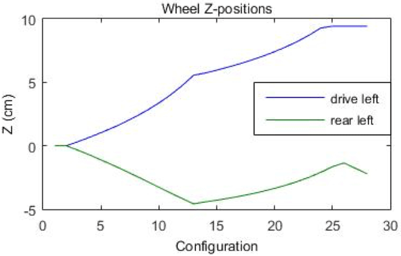
In order to investigate this behavior, the resulting wheel positions from each stepwise change in configuration were graphed for both the drive wheels and the rear casters. As for this simulation the motion of left and right wheels will be the same, only one side is shown.
As shown in figure 3, the positions of the drive and rear wheels diverge from the midpoint until the 13th iteration of the self-leveling algorithm – at which point the displacement of the rear casters changes direction. At the 25th new wheel configuration, the drive wheels run out of travel, and the rear casters again reversed direction. Changing the algorithm to account for movement of the center of the wheelbase with changes of wheel position did not eliminate this behavior.
The same slope climbing simulation was modified in order to allow the introduction of noise into the pneumatic system. After each new calculation of desired pneumatic stroke position, a random value between +0.2 inches and -0.2 inches (+/-0.5 cm) was added to each value. Along with the introduction of oscillations, the resulting error from levelness can be seen to have increased from 1.47° to 3.74°.
DISCUSSION
Simulations show the self-leveling algorithm presented here is capable of maintaining the wheelchair frame level over gradual changes in angle in both pitch and roll. Delays in reaction of the system will, however, result in the angle of incline experienced by the user being greater than the specified threshold values. Further, errors in the positions of the pneumatic actuators can introduce oscillations in the attitude of the frame. The simulation also showed the rear caster ground clearance reversing direction.
Future work will include further examination of the relationship between the algorithm and the geometric model to determine the reason for change in rear caster direction. As the pneumatic actuators are mechanical systems, errors in their displacements must be expected. A wider threshold could reduce oscillations, but may also result in greater oscillations when the threshold is exceeded. The algorithm has also been implemented on the physical prototype, and is currently being validated through real-world testing.
CONCLUSIONS
The present paper has introduced an algorithm to control a wheelchair capable of self-leveling that considers the specific geometry of its motion. Simulations demonstrate that the algorithm is effective when sources of mechanical noise are low, but that errors in movement of the mechanical system can cause oscillations that may be undesirable for users. Nonetheless, the algorithm provides a foundation for further refinement informed by additional simulations and real-world testing.
REFERENCES
Brault, M. W. (2012). Americans with disabilities: 2010. Washington, DC.
Buning, M. E., Schmeler, M. R., & Crane, B. (2006). Funding for Wheelchairs in General. Retrieved February 12, 2016, from http://www.wheelchairnet.org/wcn_prodserv/funding/funding.html#anchor10306817
Candiotti, J., Wang, H., Chung, Cheng-Shiu, Kamaraj, D. C., Grindle, G. G., Shino, M., & Cooper, R. A. (2016). Design and evaluation of a seat orientation controller during uneven terrain driving. Medical Engineering and Physics, 15(0), 1–7.
Chen, W. Y., Jang, Y., Wang, J. Der, Huang, W. N., Chang, C. C., Mao, H. F., & Wang, Y. H. (2011). Wheelchair-related accidents: relationship with wheelchair-using behavior in active community wheelchair users. Archives of Physical Medicine and Rehabilitation, 92(6), 892–898. http://doi.org/10.1016/j.apmr.2011.01.008
Cooper, R. A., Cooper, R., & Boninger, M. L. (2008). Trends and issues in wheelchair technologies. Assistive Technology : The Official Journal of RESNA, 20(2).
Daveler, B., Salatin, B., Grindle, G. G., Candiotti, J., Wang, H., & Cooper, R. A. (2015). Participatory design and validation of mobility enhancement robotic wheelchair. Journal of Rehabilitation Research & Development, 52(6), 739 — 750. Retrieved from http://www.rehab.research.va.gov/jour/2015/526/JRRD-2014-11-0278.html
Ding, D., & Cooper, R. A. (2005). Electric powered wheelchairs. IEEE Control Systems Magazine, 25(2), 22–34. http://doi.org/10.1109/MCS.2005.1411382
Edwards, K., & Mccluskey, A. (2010). A survey of adult power wheelchair and scooter users. Disability and Rehabilitation: Assistive Technology, 5(6), 411–419.
Gaal, R. P., Rebholtz, N., Hotchkiss, R. D., & Pfaelzer, P. F. (1997). Wheelchair rider injuries: causes and consequences for wheelchair design and selection. Journal of Rehabilitation Research and Development, 34(1), 58–71.
Ståhle, A., Brandt, Å., & Iwarsson, S. (2004). Older people’s use of powered wheelchairs for activity and participation. Journal of Rehabilitation Medicine, 36(2), 70–77. http://doi.org/10.1080/16501970310017432
Xiang, H., Chany, A.-M., & Smith, G. A. (2006). Wheelchair related injuries treated in US emergency departments. Injury Prevention : Journal of the International Society for Child and Adolescent Injury Prevention, 12(1), 8–11. http://doi.org/10.1136/ip.2005.010033
ACKNOWLEDGMENTS
The authors gratefully acknowledge the support of the U.S. Department of Veterans Affairs (Grant B9250-C) , the National Science Foundation IGERT program (Grant DGE1144584), and the Craig H Nielsen Foundation. The contents of this paper do not represent the views of the Department of Veterans Affairs or the United States Government.