3D Printing assisted method of manufacturing a perforated silicone Prosthetic limb liner
Esteban Ruiz, Fanying Sun, Zachary Anzelone
University of PittsburghAbstract
A perforated, double layer, silicone prosthetic limb liner has been made using a 3D printing assisted method of casting. The 3D printed parts provide a high level of detail, with minimal expense and effort. The manufacture of the prosthetic limb liner has made use of traditional liner fabrication techniques as well as newer 3D printing techniques. Platinum curing silicone was injected into a custom made four part mold to make the inner layer. Silicone was also injected into a second two part mold to make the outer layer. This method can be adapted to other applications outside the field of prosthetics and is a useful way to expand upon familiar hand skills.Introduction
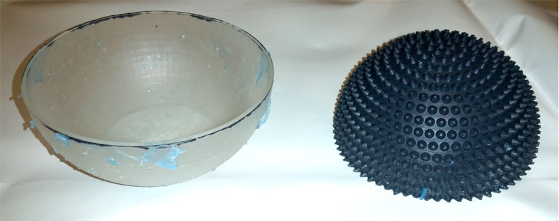
Silicone parts may be cast directly into plaster molds with no release agent. If the plaster surface is smooth it will peel off with little effort. The main advantage to plaster casting is its low cost. It can be done without expensive ovens or printers. One of the major drawbacks to plaster casting is the limited resolution for small detailed structures. When the silicone is cured and ready to be removed, it must be pulled from the mold with considerable force. Small plaster structures are easily broken during this process. In order to achieve detailed structures, such as conical perforations, a more rigid, and tough mold is required.
Materials
3D Printer
The 3D printer used for this project is the Form2 by Form Labs. It was purchased through their website. The Form2 is a desktop stereolithography 3D printer that uses an ultraviolet laser to cure liquid resin into solid plastic parts. The Form2 was purchased with award money from the Innovation Institute at the University of Pittsburgh.
Silicone
Solidworks Models for Silicone Layers
The models for making an external silicone layer includes two parts, which are a smooth outer shell and an extrusion inner shell. The sketches for the inner shell with extrusions is shown below.
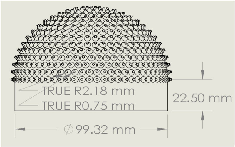
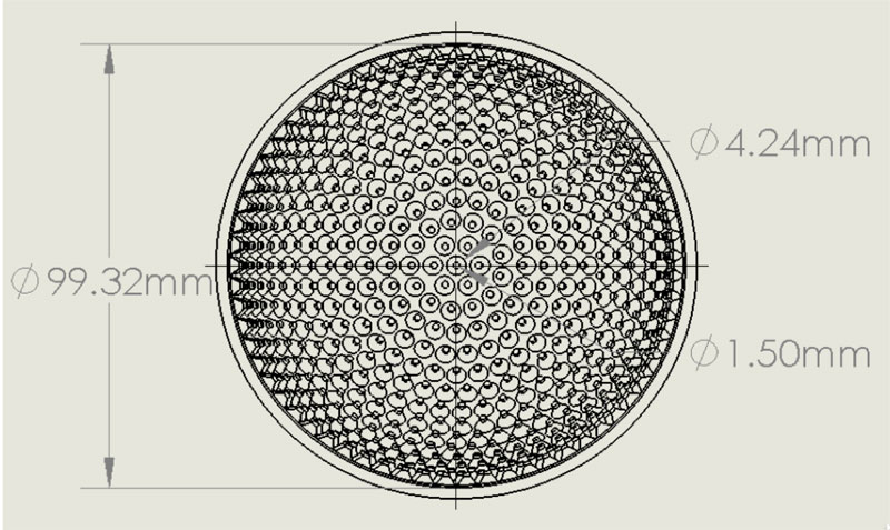
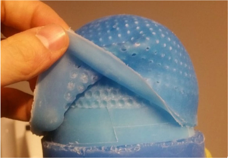
The model for making an internal silicone layer is a spherical-shaped shell which has an evenly patterned extrusion on the inside. The dimension of these extrusion is the same as those for making the external layer.\
Fabrication of outer PETG clam shell
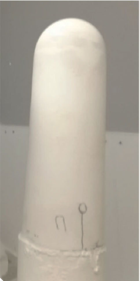
The fabrication of the positive and negative molds for the gel liner involved many processes. The first was creating a positive plaster mold with a conical outer dimension the same diameter of the finished liner’s inner dimension. This mold also has a cylindrical shape opposite to the end of the cone, and a diameter the same thickness as the finished liner’s exterior. This was used as the stable platform for fabrication.
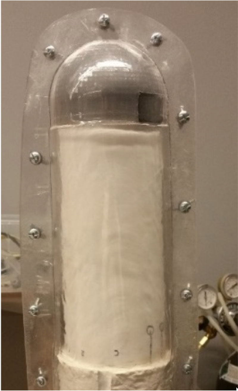
A dummy was 3D printed to the same specifications as the conical end of the finished liner. Pelite was used to simulate the thickness of the gel, and wrapped to fill between the cylindrical end and the dummy. Indentations were grooved into the cylinder to create “keys” that allow the mold to be oriented correctly. This is the finished positive model to be used for fabrication of the two clam shell pieces that form the negative model. A sheet of quarter inch PETG was heated up in the oven and draped formed over the positive model. During drape forming the PETG was folded in half around the positive mold creating a seam that bisected the mold. Once cooled the plastic was trimmed and removed from the mold. The protective film was left on the side of the PETG sheet touching the mold to allow the seam of the plastic to be separated. Holes were drilled into the seams to allow for screws and wingnuts to hold the two sections of plastic together, and allow them to be removed separately. With the positive outer and negative inner mold finished, the Pelite is then discarded and the fabrication of the gel liner can take place.
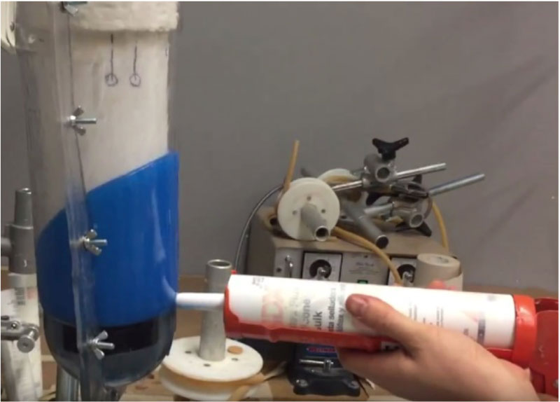
Injection of silicone
The silicone is injected into the empty space left by the Pelite between the plastic and plaster mold. The silicone must also be injected into the space between the plaster mold and the 3d printed dummy.
Discussion
Future Work
This method of manufacturing a double layer moisture permeable prosthetic limb liner using 3D printed parts to attain high levels of detail is fast and easy. As it stands now the double layer silicone liner allows air and water to pass through by virtue of it’s large perforations. A novel moisture permeable membrane must be developed which will allow water to pass through but remain air tight. This would allow users of elevated vacuum to enjoy the moisture draining characteristics of perforated liners together with the secure linkage vacuum provides.
References
Hagberg, K. and R. Branemark, Consequences of non-vascular trans-femoral amputation: a survey of quality of life, prosthetic use and problems. Prosthet Orthot Int, 2001. 25(3): p. 186-94.
Lunsford, C., Grindle, G., Salatin, B., & Dicianno, B. E. (2016). Innovations With 3-Dimensional Printing in Physical Medicine and Rehabilitation: A Review of the Literature. PM&R, 8(12), 1201-1212.