INTERPRETING JOYSTICK SIGNALS FOR WHEELCHAIR NAVIGATION
ABSTRACT
An electric-powered wheelchair that can assist people with disabilities in their mobility by avoiding obstacles is being developed for individuals who lack fine motor control or have partial vision loss. To perform obstacle avoidance, it is necessary to predict the wheelchair position over a given length of time so that the commands leading to the collision with obstacles can be avoided. The purpose of this study was to investigate the relationship between joystick signals and wheelchair motion so that dead reckoning could be implemented without installing wheel encoders or tachometers. By exploring the working mechanism of a position joystick and wheelchair kinematics, along with the experimental data, we established the relationship between the joystick signals and actual wheelchair location. The feasibility and efficacy of the result were verified empirically.
INTRODUCTION
Existing wheelchairs are primarily useful to people whose mobility problems are not combined with limited fine motor control of their upper extremities or impaired visual perception. However, such combinations of mobility, motor control and perception problems are not uncommon [3]. Therefore, an intelligent wheelchair that can assist the user in reaching his/her destination by avoiding collisions would be useful for people with severe disability [1]. In this project, a supplementary controller has been developed, which sits between the joystick and the standard wheelchair motor controller. The supplementary controller, along with its sensor network, guides the chair to avoid the obstacles sensed in its immediate surroundings with a minimum of input from the wheelchair user [4].
Unlike mobile robot navigation, the wheelchair is operated by its user via a joystick. To aid the user in avoiding obstacles, joystick signals issued by the wheelchair users sometimes have to be overridden by signals from the supplementary controller. It is necessary to predict the wheelchair position over a given length of time in response to the control signals, in order to determine whether the existing signal would lead to a collision with detected obstacles. Hong et. al [2] proposed two converting algorithms that transform two-dimensional information of the joystick to speed commands of two-wheeled vehicles. However, different wheelchair companies may adopt different approaches to transform the joystick signals. In order to determine the joystick transformation used in a particular wheelchair model (Quickie S-626, Sunrise, Carlsbad, CA), a joystick calibration study was conducted.
METHODS
A dual axis joystick is commonly used on wheelchairs where forwards-backwards movement controls both motors together and transverse movement speeds one motor and slows the other, allowing steering. Figure 1 shows the working mechanism of a typical position joystick. The joystick is essentially two rotary inductive sensors which are varied by moving the joystick handle. Two signals Cy and Cx representing the desired speed and direction are then fed into the analog to digital converters (ADC) and micro-controller, where the signals are converted to the on-duty time of the left and right motor, respectively, depending on the position of the joystick. The PWM module then generates the effective voltage input to each motor using
The wheelchair linear and angular speeds can be derived from the angular velocity of both
motors using the
kinematic relationship: 
 |
whereD is the distance between the two rear wheels and R denotes the rear wheel radius. Although we have a clear idea of how the joystick works, we experienced difficulty in transforming the joystick voltage signals into the wheelchair linear and angular velocities due to the unknown part indicated in Figure 1 using dash lines. In order to obtain information about the unknown control algorithm used by the wheelchair, we conducted some experiments to calibrate the joystick signals of the Quickie S-626.
We define forward
as the heading angle 0 degrees, right turn as 90 degrees,
backward as 180 degrees and left-turn as 270 degrees. The
full speed and direction signals from the potentiometers
are both 1.2 volt. We first calibrated the forward and backward
movements of the wheelchair. For example, setting different
speed signals while keeping the direction signal zero, we
recorded the time when the wheelchair went over a certain
distance. The next step is to calibrate the turning behavior
of the wheelchair by keeping the direction signal at a certain
value and modifying the speed signal to calibrate the relationship
between the wheelchair's pivot center and angular velocity.
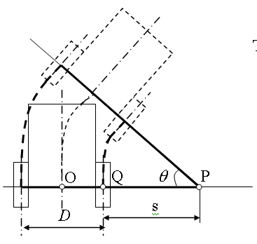
We observed that the pivot center is right in the middle
of the rear axle when the speed signal is zero (point O
in Figure 2). With the increase of the speed signal (speed<direction),
the pivot center moves from the middle of the rear axle
 to the wheel
 , and is located at
  when the speed signal is equal to the direction signal.
As the speed signal continues to increase (speed > direction),
the pivot center will move from the wheel
  to
to in the extended line of the rear axle. If we know the voltage
signals
  ,
, sent to the left wheel and right wheel, the pivot center
can be derived.
 |

The angular velocity of the wheelchair is

We then take
advantage of the experimental data to determine the relationship
between the joystick signals Cx ,Cy
and the voltage signals Vl and Vr
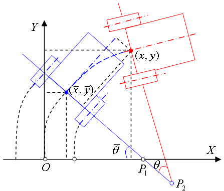
. Given the previous wheelchair position ![]() and wheelchair heading
and wheelchair heading  , we can use the following equations to estimate the new
wheelchair position (x,y) relative to the origins
as well as its heading angle
  (Figure 3).
 |
Right Turn

Left Turn

Here 
RESULTS
 |
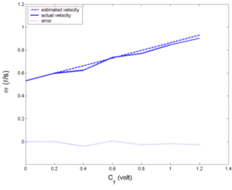
Given a series of direction and speed signals from the joystick, i.e. Cy=0.8v and Cx=[0:0.2:1.2] , the angular velocity can be estimated as shown in Figure 4. We conducted a field test in which the wheelchair position and heading were predicted given the joystick signals and time intervals. For example, if the joystick signal stayed at Cx=0.6, Cy=0.8 for 1 second and the initial wheelchair location was (0,0) with heading zero degrees, the next estimated wheelchair position would be (4, 12) with heading angle 40° . The actual wheelchair location and heading angle were approximately (4.5, 11.4) and 40° .
DISCUSSION
The experimental results show that the estimation of wheelchair configurations based on joystick signals is a feasible way to modify the analog joystick signals based on the sensor readings so that obstacles can be safely avoided. However, as the time period of the prediction becomes longer, the estimation error tends to become larger. This also indicates that the accumulation error could become a serious concern. To obtain more accurate predictions over greater lengths of time, we would need to resort to online sensors (e.g., encoder or tachometer) as well as a better dead reckoning algorithm based on these sensor readings.
REFERENCES
- Levine, S. P., Bell, D. A., Jaros, L. A., Simpson, R. C., Koren, Y., and Borenstein, J., "The NavChair assistive wheelchair navigation system," IEEE Transactions on Rehabilitation Engineering, vol. 7, no. 4, pp. 443-452, 1999.
- Hong, J. P., Shim, H. M., Jung, S. B., Lee, E. H., and Hong, S. H., "A Steering algorithm of the MCU based controller for two-wheel drive vehicles," ISIE, pp. 1887-1990, 2001.
- Cooper, R. A. "Intelligent control of power wheelchairs," IEEE Engineering in Medicine and Biology Magazine, vol. 15, no. 4, pp. 423-431, 1995.
- LoPesti, E.F., Simpson, R.C., Hayashi, S., Nourbakhsh, I. Miller, D. "Development of a smart wheelchair component system", Proceedings of RESNA 2003 (in submission)
CONTACT
Dan
Ding
Human Engineering Research Laboratories
VA Pittsburgh Healthcare System 151R-1, 7180 Highland Drive
Pittsburgh, PA 15206.
412-365-4850
dad5@pitt.edu

