ABSTRACT
Most visually impaired people can't find their way around without the use of a walking stick. Blind or visually impaired people need to get around just as much as any of us do and their only way to get around even in this day and age is a walking stick. With all of the technologies that are available today there should be a product to take the place of the long lived walking stick. Also one would think that a visually impaired person would like to look and feel normal just like anyone else (not visually impaired). There really is no alternative at this point for a blind person to use to get around. With the use of Analog infrared (IR) transmitters/receivers and some vibrating DC motors this whole process can be changed for them.
BACKGROUND
In almost every other handicap know to man there are some aides to help their handicap but for some reason there seems to be nothing for the visually impaired. This can all be changed with the use of some technology. The author has come up with the device to ultimately eliminate that traditional walking stick.
STATEMENT OF PROBLEM
The goal of this project is to aid the visually impaired to be able to detect object in their way. The sensory system was designed to provide a comfortable and discrete way for a visually impaired person to get around. This device is a combination of infrared sensors and vibrating motors, which will alert the person of upcoming objects. The sensors and motors will be mounted on a pair of shoes, which will be there eyes in detecting object in the proximity. Due to the lack of sight, the visually impaired have to use a walking stick to find object in their way. Ultimately, the sensor system will give them sense of object and normalize their lifestyle.
SUMMARY OF IMPACT
The design was intended to be used by any visually impaired person. A person of this condition should and can live a normal life but they are limited to the things they can do by themselves. They also are looked at as different and handicapped. It is hoped to change their lifestyle and make them feel like anyone else. It is believed that once they get used to this system it will feel very natural to walk around with no other aid.
DESIGN
The basic of the design is that there will be infrared sensors detecting objects which will relay that message to a vibrating DC motor. All of the components were mounted onto a pair of shoes. These vibrating motors will vary in speed according to the distance from the object. This way they client will be able to tell how far he/she is from the object. There will be 6 sensors and 6 motor (specific to each other) total, 3 of each per shoe. Having one sensor facing straight ahead, one facing diagonally up (for overhangs such as desks), and one facing to the side on each shoe. This came out to be a very good layout for many reasons. One good reason is that once a client gets used to it, they will notice that if they feel the front and upper sensor trigger at the same time and rate they will know that there is a wall. They will also notice that if just the front sensor triggers then there is a smaller object in the way. Also if the side sensor triggers and stays triggered they know they are walking along something big like a wall.
Components and Technical List
The components consist of 6 infrared sensors (which consist of a transmitter and receiver in each sensor), 6 vibrating motors, 2 battery packs (3 AAA batteries in each pack), a pair of shoes, and the circuitry. Everything will be mounted on these pair of shoes. There are going to be 3 sensors and 3 motors per shoe. Each sensor will coincide with a particular vibrating motor. And this motor will speed up as an object gets closer to it. This way the client will know from which direction the object is coming and the distance to this object.
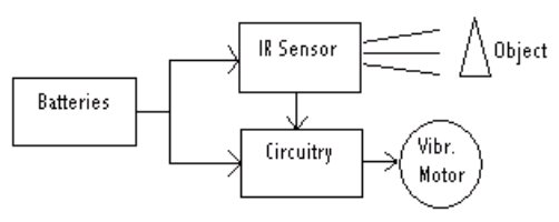 |
In order to get the sensor to talk to the motor the use of a simple negative feedback op amp circuit to increase the output voltage coming out of the sensor was used. The sensors run off of 4.7 VDC, which makes 3 AAA batteries perfect for the source.
There is going to be 1 battery pack per shoe which will contain 3AAA batteries and all of the circuitry needed to power that side of the system. The circuitry consists of 6 op amps (LM124) and 12 resistors, this is for the entire system. Therefore in each battery pack the will be 4 op amps (the LM 124 is a quad op amp, one op amp not being used), 3 AAA batteries and 6 resistors (varying in value). The front and upper sensor will be set at max distance (approx. 1 meter, which is the max distance for the sensor used) and the side sensors will be set at approx. half of the max distance. It seems to be more import to have good range on the front sensors verses the side.
Effectiveness
This design had great effectiveness with a simple design. This sensory system could detect objects in a full 180 degree path which includes upper range detection (detection at waist level). With this system a client could walk without aid and be able to sense what is around him/her from a meter in front, a half meter to each side, and a meter up at waist level. This, once accustom too, can be a stand alone alternative for the visually impaired.
DISCUSSION
This product has the potential to change the lifestyle of many visually impaired individuals. It is currently in use by a client that was worked with, and that lives in Lowell. The design has been made relatively simple in order to be less bulky and can be reproduced very inexpensively. This product has great potential to do great things for the blind and visually impaired.
The Sensor System for the Blind is very compact and simple, there are not loose wires and can be used by anyone. The only variation per person would be the change in shoe size.
ACKKNOWLEDGEMENT
This project was designed and developed with the support of the Electrical Engineering Department at the University of Massachusetts Lowell. The acknowledgement of Prof. Donn Clark and Prof. Alan Rux of the Assistive Technology program at the University of Massachusetts Lowell must be had for their support.