PATIENT ATTENDANT CALL
ABSTRACT
Patients with ALS have impaired muscle and speech movements and need a personal attendant to assist them. The commonly used communication devices do not differentiate between emergency and non-emergency case adding stress on the attendant. The prototype device sends multiple messages between the patient and the attendant. The attendant also has the option of turning off the audio and vibrate alert.
BACKGROUND AND PROBLEM STATEMENT
ALS (Amyotropic Lateral Sclerosis) occurs due to degeneration of motor neurons in brain and spinal cord. Due to ALS, muscles become impaired which results in difficulty in lifting, bathing, speech, etc (1). As the disease progresses people affected with ALS have a constant need for a personal attendant. Communication between the attendant and patient is commonly accomplished with a simple device such as a doorbell buzzer. The patient presses the switch next to the bed and the buzzer (carried by the attendant) makes a noise to alert the attendant. The attendant is unable to differentiate between an emergency case and a non-emergency case when he/she is buzzed. At times this would add additional tension on the attendant and as consequence would affect the manner with which the patient is assisted.
We have developed a device that improves the communication between the patient and the attendant by providing three different messages the patient may send to the attendant. For example. possible messages are "Help", "Water" and "Restroom". These messages are written on slips of paper and attached to the patient and attendant units. They can be changed at any time. Additionally three audio messages can be recorded at any time that corresponds to the transmitted messages.
DESIGN AND DEVELOPMENT
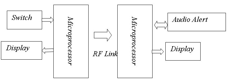
The device consists of a patient unit - attendant unit (also referred to as transmitter-receiver pair). The patient selects the message he/she wants to send to the attendant by depressing the switch. The selection is sent to the attendant unit, which alerts the attendant by highlighting the message while playing the appropriate audio message.
 |
I. Patient Unit
Any commercial switch plugs into the 1/8" jack on the patient unit. The switch on the unit can be replaced depending on the need of the patient. The unit receives its power supply from a commercial wall transformer. A Basic Stamp 2 microprocessor (Parallax, Rocklin, California) is used to scan the input from the switch. The patient can make a selection by keeping the switch pressed till his/her choice is highlighted on the display panel.
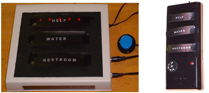
The display consists of three banks of LEDs arranged in parallel rows of five each. The current signal from the microprocessor is amplified by use of NPN transistor 2N2222A to each of the LED banks. The messages are placed over the LED's and are highlighted when the LEDs flash. Each message is coded with a numeric value. On selection of the message the numeric value is transmitted using a 418 MHz RF communication board (Parallax, Rocklin, California). The default message on the unit is "Help" and it is activated even when the switch is pressed for an instant. Additionally, LEDs flash in sequence when no switch is detected on the unit. The programming for the microprocessor was done in Parallax PBasic. The patient unit is shown in Figure 2.
 |
II. Attendant Unit
A rechargeable 9V battery powers the attendant unit. The unit is light, durable and handheld. A Basic Stamp 2 microprocessor integrates the various operations of the unit. The unit has a 418 MHz RF receiver board. On receiving the numeric code from the transmitter, the microprocessor activates the voice recorder chip (Winbond, San Jose, California). The voice recorder plays back the selected pre-recorded message on the speaker. The current signal from the microprocessor is amplified with NPN transistor 2N2222A and is used to power the LED banks.
Depending on the numeric code received, the appropriate display lights on. The display on this unit consists of an LED next to each typed message. The messages are placed next the LEDs. Individual messages are recorded on the voice recorder chip. A volume knob is used to control the volume of the recorded message. The programming for the microprocessor was done in Parallax PBasic. The attendant unit was shown in Figure 2.
EVALUATION
The device evaluation consisted of presentation to an audience of therapists, biomedical engineers and non-technical people. The device was found to operate satisfactorily during the demonstration.
DISCUSSION AND CONCLUSION
The device works well and as intended. The patient is able to communicate specific messages to the attendant. The attendant is aware of the patient needs and is able to work in a more calm and relaxed manner. Depending on the attendant, audio alert can be turned on or off. Since the number of non-emergency instances is more than the emergency instances, this device would significantly reduce the tension on the attendant. Both units are easy to operate and it takes very little time to learn to operate it. Work is currently on to replace the LEDs in the attendant unit with a LCD panel, making it more compact and easy to read. Messages on both units can easily be changed to suit the patient needs.
REFERENCES
1. Website: www.als.org
ACKNOWLEDGEMENTS
NSF Grant BES-9981867 provided funding. The author wishes to thank Kevin Caves and Richard Goldberg for his suggestions during the development of this device. The author also wishes to thank Vinay Tannan for his assistance in rebuilding this device and implementing the audio message feature..
Author Address
Swaroop
S. Singh
152 MacNider Hall,
University of North Carolina,
Chapel Hill, NC-27599-7575
Email: swaroop@unc.edu