Powered Swingaway Mount for Independent Positioning of Environmental Control Unit
ABSTRACT
A Powered Swingaway Mount was designed to allow automated positioning of an environmental control unit. A 45-year-old consumer with C4-5 level SCI was interested in independently positioning an environmental control touch screen in front of his wheelchair for access, and then independently stowing the device at the side of his chair. While many commercially-available mounts include a swingaway feature, most require manual operation by the user or caregiver. Because of the consumer's limited range of motion, independent positioning of the touch screen required an automated system.
KEYWORDS
Powered swingaway mount; mount; environmental control; swingaway; rotating; motorized
BACKGROUND
Commercially-available mounts are commonly used in the field of Assistive Technology to secure augmentative communication devices or laptop computers to wheelchairs. However, these devices are generally not motor-driven. These commercially-available mounts are commonly secured to the wheelchair frame and manually adjusted at the joints for proper positioning, including adjustments to angles, height, and swingaway function. In this case, the consumer was interested in a design which would allow him to independently access his device and then safely swing it out of the way, to allow access to tables, his computer desk, and to transfer out of the wheelchair. To enable independent control of the device, the swingaway mount would have to be motorized and switch-operated.
While not mass-produced, powered mounts have been designed for custom application in the field of Assistive Technology. One such mount was designed by Prentke-Romich Company, which allowed a user to reposition his laptop through the use of two switches. (1) Another custom mount was designed by students from the Robotics and Automation Laboratory at the University of California at Irvine, which allowed a person to reposition an Augmentative Communication device by activating a single switch. While this device was successful, the design did not extend beyond the prototype phase. (2)
APPROACH
 |
|---|
Because existing designs were unable to meet all of the consumer's needs, it was determined that a new custom design was required. Design parameters included switch-activation, powering off the wheelchair batteries, safely stowing device alongside the chair when not in use, and allowing access to tables and desks. Funding for the mount was not an issue, which provided designers and engineers the freedom to explore many different ideas. It was determined at the outset that the motorized mount would need to travel in a helical fashion, in order to begin in front of the user and end up alongside the chair, clearing armrests and preventing obstruction to tables. However, without a CNC plasma cutter available, defining and controlling the helical movement proved most challenging. A system of rotating, telescoping stainless steel tubes was devised, which is described below.
DESIGN
 |
|---|
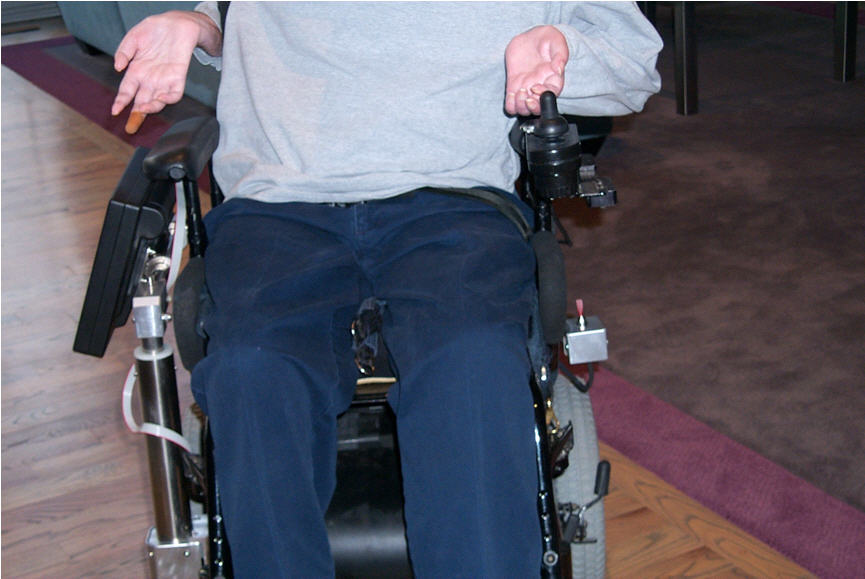
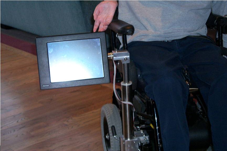
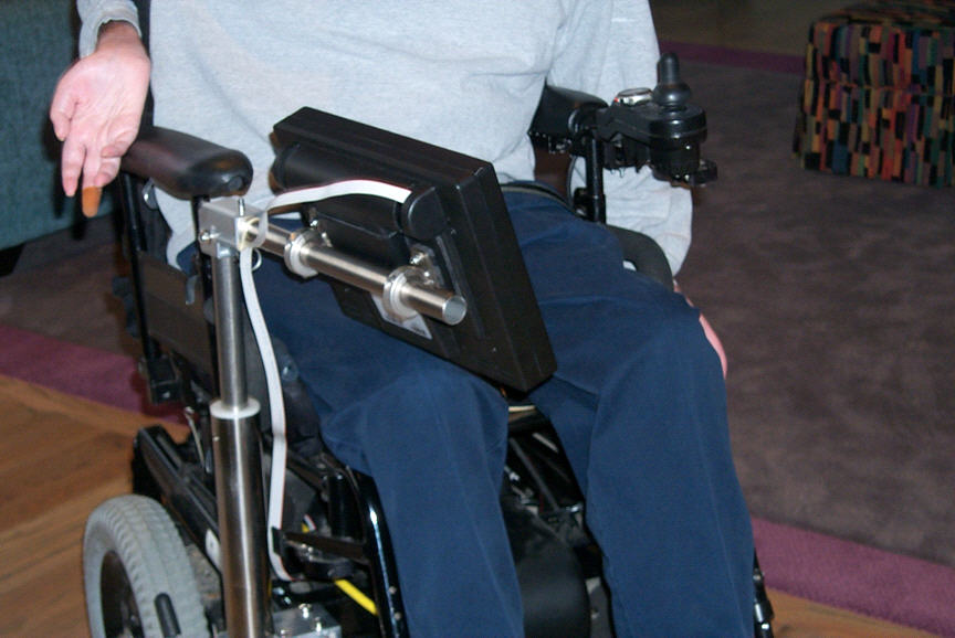
The Powered Swingaway Mount consists of a system of concentric tubes that rotates 270-degrees while traveling 10" vertically, allowing an Assistive Technology device to automatically be repositioned for access by the user. The swingaway mount is powered by a 24VDC motor running off two 12VDC wheelchair batteries. A threaded rod, coupled to the 24VDC motor, causes a threaded stainless steel tube to move in a spiraling motion. A steel pin pressed into the wall of the tube rides along a track, welded to the inside of a larger diameter tube. The track controls the travel of the system, causing the inner tube to ascend 10" while rotating 270-degrees. A horizontal arm, connected by a 90-degree elbow, provides a simple attachment site for an augmentative communication device, laptop, or other device. In this application, the user's environmental control touch screen mounted to the arm stops within reach of his fingers at the end of travel. In the opposite direction of travel, the touch screen lowers 10" vertically and is safely tucked alongside the client's wheelchair, allowing him to pull up to tables, transfer out of his chair, etc. The motor is mounted to the base frame at the side of the client's wheelchair, and coupled to the tubing system via a pair of stainless steel collars. The motor is actuated by a momentary DPDT switch, mounted off the left armrest of the wheelchair, requiring the user to hold the switch for the desired length of travel. Pushing the switch in one direction causes the arm to rise; pushing the switch in the opposite direction causes the device to lower.
 |
|---|
DISCUSSION
The Powered Swingaway Mount was implemented to the user in October 2002. Simple adjustments after the initial implementation included repositioning the switch to accommodate seatbelts when traveling, replacement of the motor after the switch was caught in the "on" position (see aforementioned seatbelt), and resecuring set screws, which loosened over time.
The user has reported much satisfaction with the design and has offered to present the mount at local and national conferences. As of December 2003, the Powered Swingaway Mount is functioning successfully and is used nearly everyday.
 |
|---|
COST
The Powered Swingaway Mount is comprised of a combination of custom-designed, custom-fabricated parts and standard industrial components, totaling approximately $400. Significant costs included the custom attachment to the user's wheelchair frame and the design and fabrication of the helical track, which was accomplished using a combination of angle grinders and plug welds. Design and fabrication time is estimated at 56 hours, with an additional 4 hours of implementation and adjustment time. Estimated total cost of design, including labor and material costs: $5,000.
REFERENCES
- http://www.aacinstitute.org/bromich/poweredmount/poweredmount.html
- McCarthy, M. & Ruth, D. (1999). A wheelchair-based mounting system for automated positioning of an electronic augmentative communication device. Proceedings of the RESNA '99 Annual Conference, USA , 367-369.
ACKNOWLEDGEMENTS
The Assistive Technology Unit at the University of Illinois at Chicago would like to acknowledge Mr. Brian Pullin, MS, for his contribution to the design of the Powered Swingaway Mount.
CONTACT
Dana Mavros, MS, ATP, RET
Assistive Technology Unit
Institute on Disability and Human Development
(M/C 626)
University of Illinois
at Chicago
1640 West Roosevelt - Room 408
Chicago, IL 60608-6904
(312)413-1555 (ATU Main Office)
(312)413-1554 (TTY)
(312)413-3709 (Fax)