THE FURTHER DEVELOPMENT OF A USER-FRIENDLY EXERCISE SYSTEM FOR WHEELCHAIR USERS
ABSTRACT
Exercise opportunities for manual wheelchair users (MWU) are limited, and daily wheelchair propulsion is not adequate to sustain cardiovascular fitness (1). Cardiovascular disease is an increasing health concern for MWU because of their sedentary lifestyle. There is a pressing need to provide both the tools and the environment to make exercise for a MWU more desirable. The Game wheels exercise system was developed to fill this need. An electronic interface between a set of instrumented rollers and a personal computer allows a MWU to use their wheelchair as a joystick to play video games. During initial testing, users were asked for comments regarding their likes and dislikes of the system. The results of those comments were summarized and a program was developed to incorporate the changes into the Game wheels system.
BACKGROUND
The original Game wheels system proved to be an effective means of inducing MWU to exercise on a regular basis. (2) However, surveys completed by original test subjects pointed out shortcomings in the system. It was the purpose of this program to develop solutions to those shortcomings and to incorporate them into the Game wheels system.
The following three items were considered the most prominent concerns:
- Allow the system to accommodate a wider range of chairs. The original system had limitations as to the width of the chair that it would handle.
- Develop a roller system with a more realistic feel at startup and coast down. The original system used a single roller for each side of the system. To maintain a low profile, the rollers had to be small in diameter (approximately 4 inches). The small diameter did not allow for sufficient mass in the rollers for them to feel realistic
- Implement a simple mechanism to allow the user to load, unload and anchor themselves to the system independently. The original system required the help of another person to secure tie down straps that stabilized the user's chair while using the system.
DESIGN APPROACH
To address the problem of accommodating a larger range of chairs, the width of the rollers was increased from 6in.(15cm) to 13in.(33cm) with a larger gap between the rollers. The new system will now accommodate a track width up to 30in.(76cm) wide as opposed to 24in.(61cm) for the original system.
 |
The original system did not react realistically. Despite having the ability to increase pushing resistance, there was no ability to control coast down. The problem was that the speed of the original rollers deteriorated too rapidly and to compensate, the user had to increase their push frequency to an unnatural level. To allow the rollers to feel and react more realistically, there had to be an increase in the mass of the roller system. Adding mass to the rollers was explored, but results were not adequate. The mass needed to be further from its center of rotation to increase the inertia of the system to have the desired effect. This proved impractical because increasing the roller diameter would increase the profile height of the overall system. This would cause repercussions throughout the system by adding length to the loading ramp and larger size to the entire system. The approach taken was a pair of belt driven flywheels with their axes at 90 degrees from the roller axis. (See figure 1)
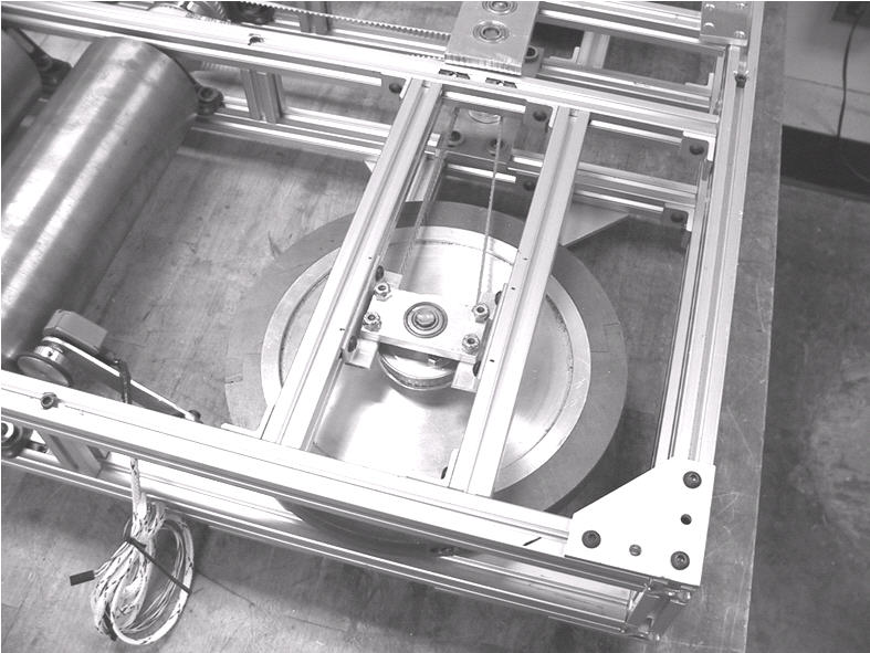 |
The flywheels could be made with a large enough diameter to allow the mass to be a greater distance from their center of rotation to allow realistic resistance at startup as well as a more realistic coast down period after each push. The flywheels were fabricated from a central aluminum disc approximately 9in. (23cm) in diameter with a steel ring 1in. (2.5cm) thick and 1in. (2.5cm) wide attached at the outer edge. Each of the two flywheel assemblies weighed approximately 13lb. (6kg) with 9lb (4kg) concentrated at the outer rim. (See figure 2)
This concentration of weight at the perimeter of the flywheel provided the system with an adequate amount of resistance at startup, but stored sufficient energy during operation that the coast down became more realistic. The flat orientation of the flywheels allowed the profile of the entire system to remain slim.
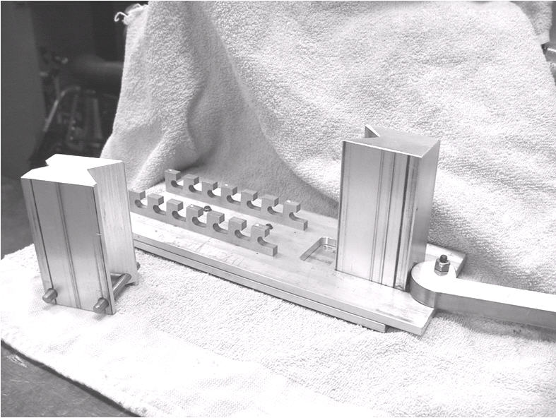 |
The self-loading feature was perhaps the most challenging aspect of the redesign. The original system used a two-roller system where each of the rear wheelchair wheels was positioned at the crest of one roller. A series of tie down straps maintained the position of the wheelchair. It was decided to change to a 4-roller system where the main wheelchair wheels would ride in the trough between two rollers and the casters would be used to locate and secure the wheelchair in position. One preliminary idea was to use a type of foam padding on the surface of the system to maintain the position of the casters. An early trial of this idea proved unfruitful, as the wheelchair was not stable enough to maintain position on the rollers. Other methods of securing the casters were tried, but none allowed the MWU to anchor the chair independently. Finally, an adjustable locking mechanism was developed to accommodate various caster sizes. This mechanism consisted of two sliding plates with two toothed racks that anchor a stop block to the system. An opposing block that slides by way of a lever operated cam locks the caster in place.
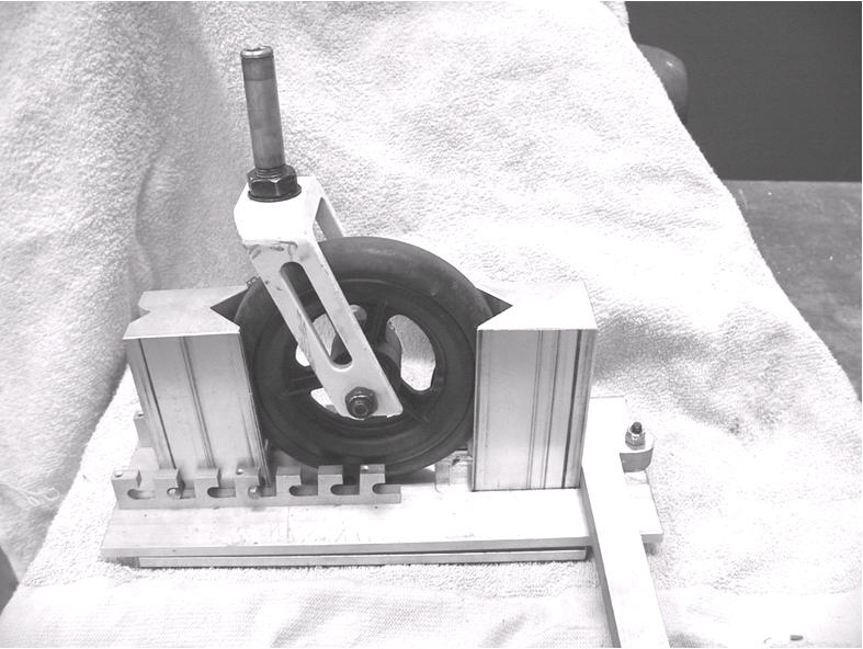 |
This assembly is in turn held in place on the platform by Velcro pads fastened to the underside of the caster clamps and the surface of the Game wheels system. The user can position the caster clamp assembly on the system during the initial setup procedure. To mount the system, the MWU rolls over the main set of rollers. The toothed racks act as guides to position the casters. Once in position, the stop block is inserted and the cam lever locks each caster in place.
CONCLUSION
Initial trials of the revised Game wheels system have shown that it is now possible for a MWU to setup and use the system independently. The prototype caster clamp system is currently fabricated from aluminum parts, but could be produced as a much lighter plastic assembly. The system has a more realistic feel and the system now accommodates a wider range of manual wheelchairs.
Refinement is still ongoing and will continue until the system ultimately becomes available for purchase and use in rehab institutions as well as MWU homes.
REFERENCES
- Janssen, T.W.J., Van Oers, C.A.J.M., van der Woude, L.H.V., &Hollander, A.P. (1994) Physical strain in daily life of wheelchair users with spinal cord injuries. Med. Sci Sports & Ex, 26(6):661-670
- O'Connor, T.J. et al , (2002) Kinetic and physiological analysis of the GAME wheels system. Journal of Rehabilitation Research & Development, 39(6): 627-634
Author Contact Information:
William A. Ammer, BS,
University of Pittsburgh,
Human Engineering Research
Laboratories,
7180 Highland Drive 151R-1,
Pittsburgh, PA 15206,
Office Phone
(412) 365-4858
EMAIL: ammer@pitt.edu