A Study on the Balance Function of the IBOT™ Transporter
ABSTRACT
The purpose of the study was to examine the balance function of INDEPENDENCE™ 3000 IBOT™ Transporter under the influence of different loads and different seat heights. Four force plates were placed underneath the IBOT™ Transporter to record the forces and moments during the transition phases of the balance mode. A load cell placed on the side recorded the force exerted by the operator at the moment of initiating the balance function. The Optotrak motion analysis system was used to track the movements of the wheels and seats through the balance mode. A total of 27 trials (three loads, three seat heights, three trials of each) have been collected. The results of this study indicate that when the IBOT is at the middle seat height or with an extra 20 lb backpack, it takes significantly less force for the operator to initiate the balance function. Also, an extra 20 lb load on the lap increases the difficulty of initiating the balance function.
KEYWORDS
IBOT™ Transporter, balance function, load, seat height.
INTRODUCTION
 |
|---|
The INDEPENDENCE™ 3000 IBOT™ Transporter (IBOT) is a powered, multi-functional wheeled mobility system, which provides the opportunity to enhance mobility. The IBOT design incorporates advanced electromechanical systems and control systems to achieve five operationally distinct mobility functions, (1) standard function, (2) four-wheel function, (3) balance function, (4) stair function, and (5) remote function. In balance function, only one pair of drive wheels makes contact with the ground. The second pair of drive wheels is positioned directly above the ground-contacting drive wheels. The balance function provides mobility at an elevated seat height. In balance function, the system uses the I-Balance Technology to actively maintain stability by driving the wheels to stay under the user. Pitch, wheel position, wheel velocity, and other sensor data are processed along with the user's joystick commands to provide the desired speed and direction while maintaining stability on two wheels. In a study by Cooper et al. [1], subjects reported using the IBOT to perform a variety of activities including holding eye-level discussions with colleagues and shopping by balancing on two wheels. The purpose of this study was to investigate effects of different loads and seat heights on the balance function of the IBOT and thus provides a more intuitive idea about how the balance function works for the potential users and clinicians who prescribe this device.
METHODS
 |
|---|
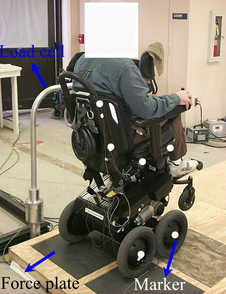
The experimental setup includes four force plates (two from Advanced Mechanical Technology, Inc. and two from BERTEC Corp.), a load cell (Advanced Mechanical Technology, Inc.) and an Optotrak motion analysis system (see Figure 1).
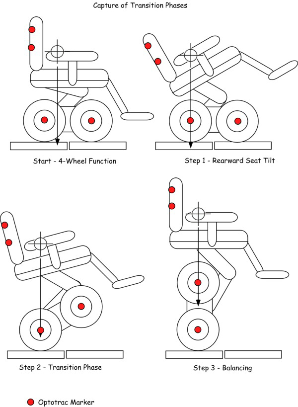
All these devices were triggered by one single switch to ensure the data obtained from different devices were synchronized. A wooden platform was constructed to house the four force plates, which sit flush within the platform to ensure a level surface and were used to collect kinetic data, i.e. force s and moments. The IBOT was initially set to its four-wheel function with each wheel being placed on a single force plate. The IBOT used in the experiment was calibrated for the operator who has a thorasic spinal cord injury. A load cell placed on the side provides support for the operator when he initiates the balance function and returns to the four-wheel function, and records the forces exerted by the operator as well. The Optotrak motion analysis system traces the infra-red markers placed on the wheels and frame of the IBOT during the whole process. The test protocol included three loads, i.e. nominal load (i.e. the operator), 20lb extra backpack, 20lb extra brief case on the lap of the operator, and three seat heights, i.e. low, medium ( i.e. the middle value of the maximum permissible height and the minimum height) and high. Three trials for each load were performed at each seat height. In each trial, the transition phases from the four-wheel function to the balance function were recorded (see Figure 2). A total of 27 trials were collected and analyzed.
RESULTS
For each load and seat height, mean peak forces for three trials acting on the load cell during the balance function were obtained in Table 1.
Mean peak force exerted upon the load cell (lb) |
Low seat height |
Medium seat height |
High seat height |
|---|---|---|---|
No load |
23.6 |
16.8 |
20.3 |
20lb backpack |
19.0 |
16.9 |
15.4 |
20lb brief case |
24.7 |
18.5 |
20.7 |
 |
|---|
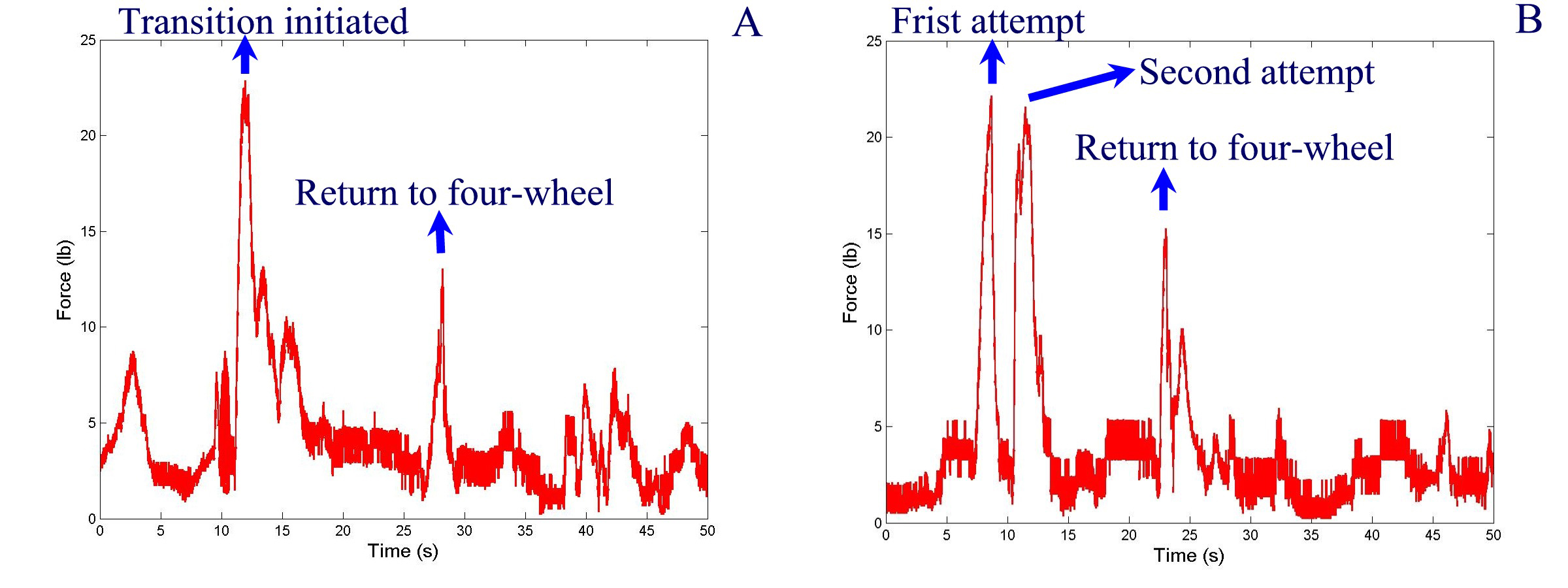
The peak force usually occurs at the moment when the occupant transits from the four-wheel function to the balance function. Figure 3 plots the forces exerted by the operator during the balance function, where Figure 3A describes the forces when the IBOT was at the low seat height and with a nominal load and Figure 3B describes the force when the IBOT was at the high seat height and an extra 20-lb brief case.
 |
|---|
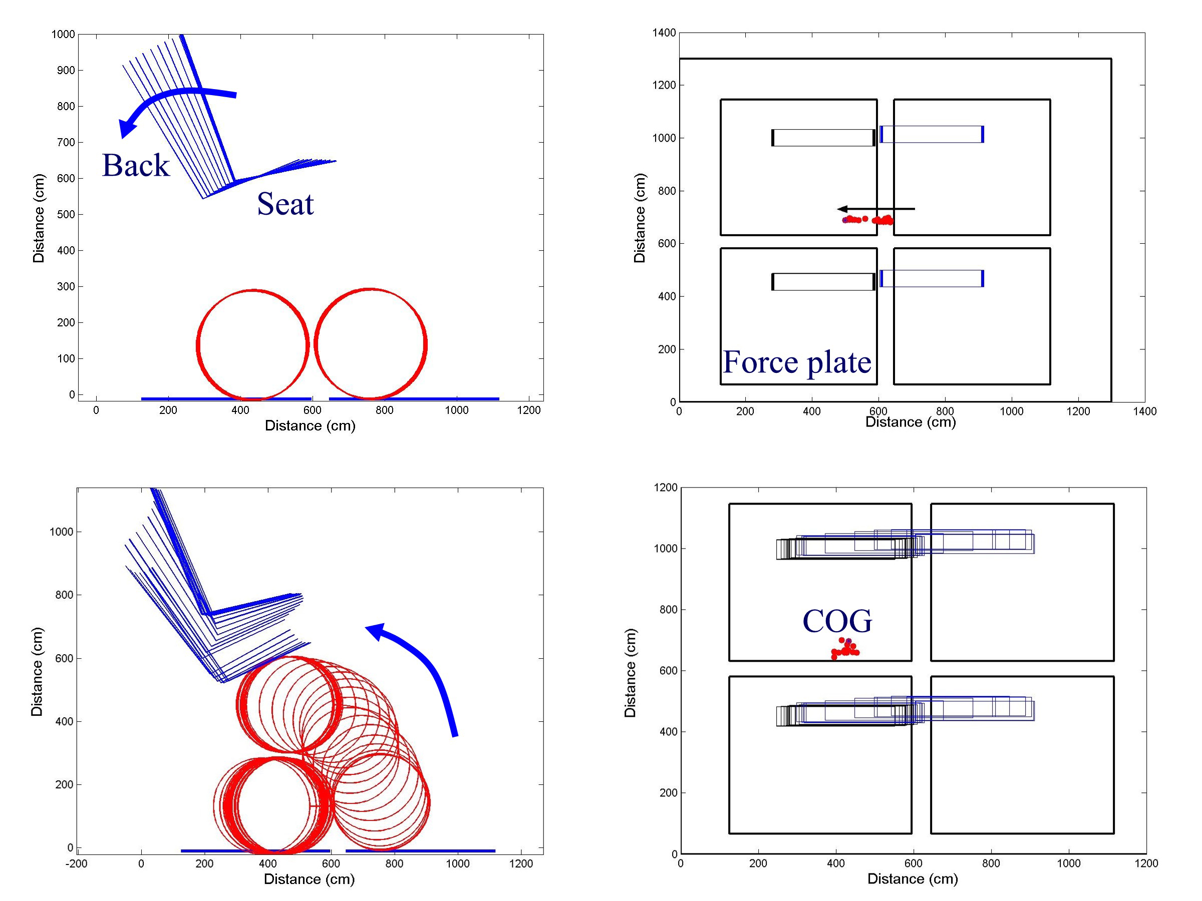
Figure 3 plots the change of wheelchair posture and the center of gravity (COG) during the balance function at the medium seat height and normal load, where the four squares represent the force plates and small dot represent the center of gravity.
DISCUSSION
From Table 1, the operator of the IBOT had to exert about 20-lb force on the support rail when initiating the balance function from the four-wheel function. Univariate analysis of variance was used to identify significant difference in the force exerted upon the load cell among different seat heights and loads. The Bonferroni post-hoc analysis was used to identify significant interactions of individual seat heights and loads. The analysis was performed using SPSS with a significant level of 0.05. The result indicated that there is no significant iteration between the seat height factor and load factor (p=0.22), so we could look at the two factors independently. The extra 20-lb backpack was found to be significantly better than the nominal load (p=0.015) and the extra 20-lb brief case (p=0.009) in reducing the forces needed to initiate the balance function. As the IBOT was calibrated for the operator, it is supposed to have better performance with the nominal load. However, the calibration was conducted several years ago and the operator's weight changed, so the nominal load used in the experiment was not optimal. We also found that the middle seat height was significantly better than the low seat height (p=0.007) in terms of forces exerted on the load cell for initiating the balance function. Although no statistical significant difference was found between the high seat height and low seat height (p=0.055), Table 1 showed relatively large difference between the mean peak forces for these two seat heights.
From Figure 3, we can tell that the extra 20-lb brief case on the lap increased the effort to raise the two front wheels. We did have two cases when the seat was set to the maximum permissible height and 20-lb brief case was put on the operator's lap, it took the operator more than one try to balance on two wheels (see Figure 3B where two peak forces occurred before 15s represented two attempts to lift the front wheels). The other peak between 20s to 25s was generated when the operator returned the chair to the four-wheel function.
From the two upper figures in Figure 5, the first step to the balance function was to tilt the seat rearward so that the center of gravity moved almost to the middle of the rear axle. The bottom two figures in Figure 5 shows the transition from four wheels to two wheels, where the center of gravity stays almost in the middle of the rear axle by constantly moving the rear wheels back and forth. The movement of the center of gravity during the transition phase was small with the lower and medium seat height compared with the maximum seat height, and the same is true with the nominal load and extra backpack compared with the extra brief case.
It is suggested that extra loads should be placed in the form of the backpack instead of the brief case if necessary, and more space is needed in case of the extra load and higher seat height when initiating the balance function.
REFERENCES
- R. A. Cooper, M. L. Boninger, R. Cooper, and A. R. Dobson, "Technical perspectives: use of the Independence 3000 IBOT Transporter at home and in the community," Journal of Spinal Cord Medicine , vol. 26, pp. 79-85, 2003.
- Cooper, R. A. Intelligent control of power wheelchairs, IEEE Engineering in Medicine and Biology Magazine , vol. 15, no. 4, pp. 423-431, 1995.
ACKNOWLEGEMENTS
The work is supported in part by the National Institute on Disability & Rehabilitation Research, and the Rehabilitation Engineering Research Center (#H133E990001).
Author Contact Information:
Dan Ding,
Human Engineering Research Laboratories,
VA Pittsburgh Healthcare
System 151R-1,
7180 Highland Drive,
Pittsburgh, PA 15206.
412-365-4850,
dad5@pitt.edu