Design of Device to Assist in Label Separation
ABSTRACT
An ability many people take for granted every day is their ability to easily use their hands. It is a wonderful ability that helps us open jars, write, or peel a label from its backing. What does a person do when they no longer have these fine motor skills and find even the simplest tasks to be difficult? Technology becomes their friend. Devices are made everyday to assist people in their everyday tasks so that they might be able to perform everyday jobs. This is where a label dispensing device has shown up as a need. This need leads to a device that will accept a sheet with three labels spanning 11 ½ - in and dispense the label so that there is no fuss getting the label off of its backing. The label comes off flat and in one piece.
BACKGROUND
The Rolla Area Sheltered Workshop is a local business that employs people with special needs. They perform various functions for different companies. One of their services is recycling shipping boxes for Wal-Mart. This involves placing a black label over a barcode on the outside of the shipping box. The boxes and labels are supplied by Wal-Mart. There is a small team of two or three individuals who divide the work amongst themselves. The tasks required to complete this job include stacking the boxes, locating the barcode, peeling the labels, and applying the label over the barcode. The problem arose that some potential employees that the manager at the workshop would like to hire have difficulty with fine motor skills and are unable to remove the labels from the backing sheets. The goal of this project is to design a device to pre-peel the labels from their backing to make removal easier. The device must use the labels supplied from Wal-Mart and must only peel the labels, not apply them to ensure work for the employees.
METHODOLOGY
The procedure followed during the product design consisted of gathering customer needs, using multiple concept generation techniques, selecting critical issues for concept selection, and building prototypes.
Customer Needs
Interviews were conducted with the managers and employees at the Rolla Area Sheltered Workshop. During these interviews, only one employee had a need for a device to assist in the removal of the label. He found it hard to hold the paper steady as he removed the label. This resulted in crumpled labels at times. This required a device which would assist the working in peeling the label.
The other employees found it to be a very simple task with no need to improve the procedure. This caused most of our customer needs to derive from the manager and supervisors. During the interview with the manager, it became apparent that this device was not mainly to assist the current workers, but the potential workers with limited use in both arms. This required the device to be functional with only one arm and by either side.
Since the labels arrive at the Workshop stacked in a box 12 x 12 ½ x 5 from Wal-Mart the device had to accept this sheet size. The size of the sheets also required that the device be stationary. It was not desired to have a person of limited mobility carry the device around.
Safety was found to be a very important customer need since the people operating the device were physically as well as mentally disabled. The device could not have any sharp edges or pinch points exposed to the workers.
Concept Generation
Numerous methods were used to generate a variety of concepts. Over fifty concepts were created by just drawing an idea, using the C-sketch method, developing a morphological matrix, and using design by analogy. The C-sketch method consisted of letting each team member make improvements and changes to a concept. The initial concept was passed around from team member to team member until each had made their mark on a design.
The morphological matrix related functions to device parts in a functional matrix. The functions of the label dispenser are compared to the functional matrix and parts are listed which perform the required functions. This technique led to concepts incorporating fanned blades and wedges for label separation.
Design by analogy related whole devices to their functions. These products were then ranked in their similarity to the label dispenser. The dispenser was found to be related to a vacuum, cheese grater, food processor, and pencil sharpener. Designs were then developing using similar parts from these devices. One design used a vacuum to suction the labels off of the backing.
Concept Selection
The critical issues for the selected device are the peel efficiency (percentage of labels peeled from the sheet) and the percent of the individual label peeled. With over fifty concept ideas, a broader criteria basis was required. For each design concept, calculations were made to evaluate the cost, maintenance requirements, ease of use, safety, simplicity, ease of manufacturing, noise, power consumption, and separation efficiency. The separation efficiency was unable to be calculated. This required that tests be performed to view the ability of each separating mechanism. Each of the criteria was weighted in importance. The concepts were then ranked and the final design concept selected.
 |
|---|
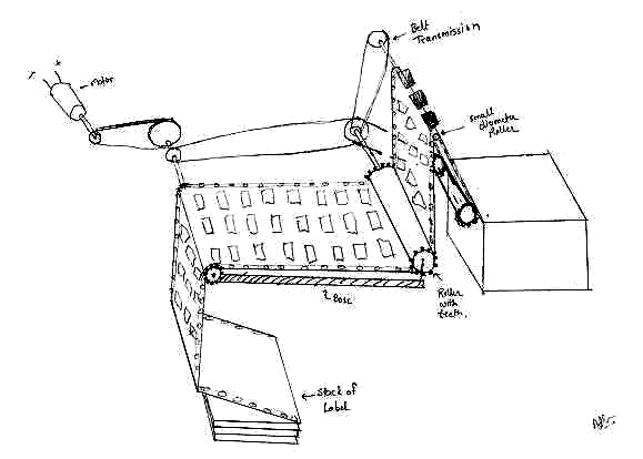
Shown in figure 1 , the final concept chosen uses a small diameter roller to separate the label from its backing. An electric motor drives a belt driven system which in turn drives two sprockets which advance and guide the label sheet through the system. A pair of friction rollers is located on either side of the small diameter separation roller. This provides the tension necessary for reliable separation. The device stops when the row of three labels is partially peeled and exposed for removal by the operator. When the final label is removed from the row of three, the operator can then either advance the next set of labels using a large push button, or if the device is in automatic mode, simply wait for the machine to advance the next three labels and continue removing them from the sheet.
Proof of Concept Prototype
 |
|---|
A simple cardboard device shown in figure 2 was used to demonstrate that the chosen concept would satisfy the two most critical issues for the device: peel efficiency and percent of the label peeled. A single strip of labels was used to test the device. The parts tested were the small diameter roller and tension devices. Without the proper tension, the paper will simply slide over the small diameter separation roller without peeling the label if there is too little tension or it may rip the paper if there is too much tension. The used of a small diameter roller was an important test factor since the paper may rip if the diameter is too small or not remove the label at all if the diameter is too large. The proof of concept prototype performed well; More than 80% of each label was peeled from the backing, and the only labels that were not peeled were those sacrificed to loading and unloading the device.
Alpha Prototype Design and Construction
 |
|---|
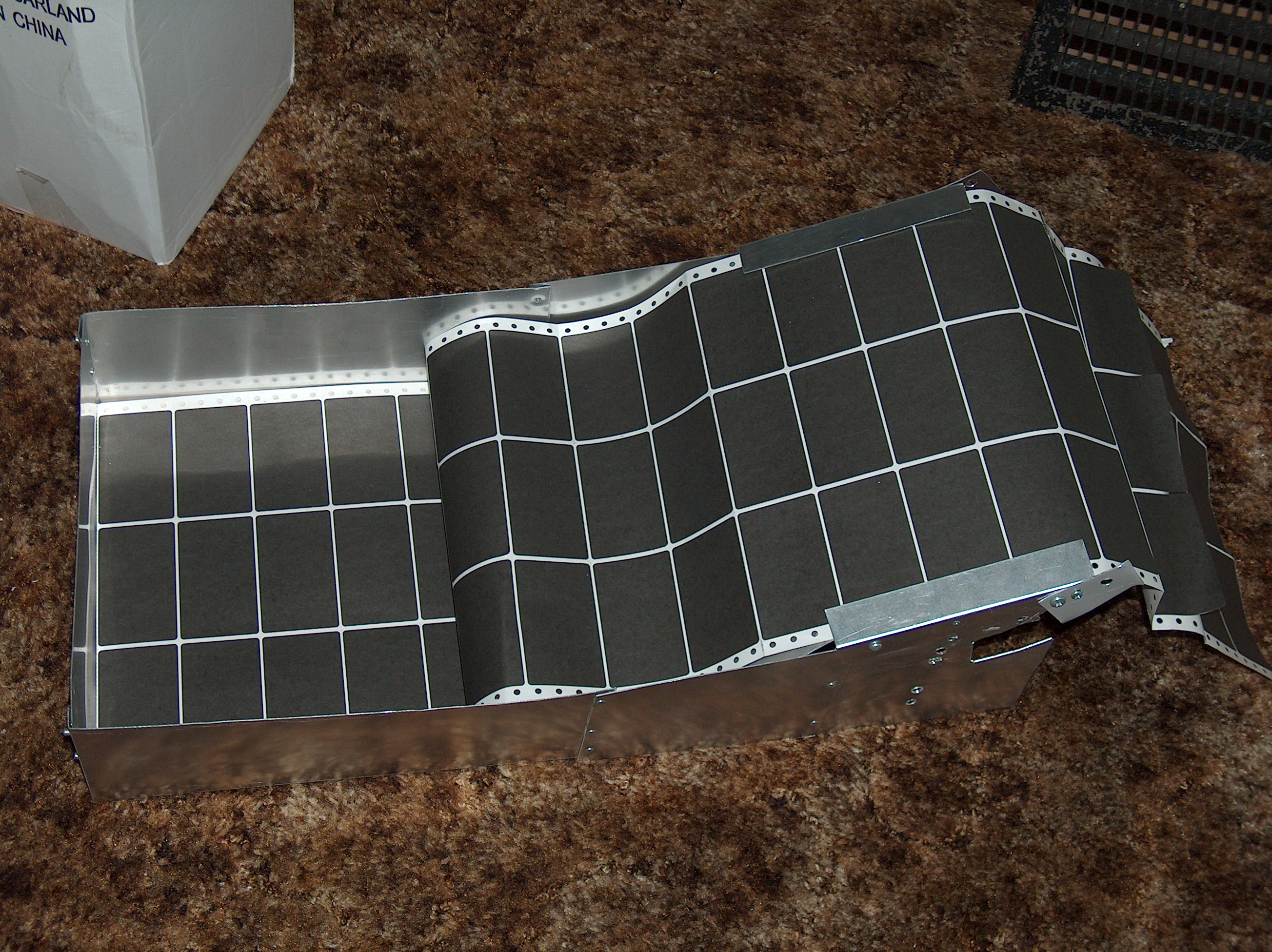
An alpha prototype was constructed to test the chosen concept. The prototype was constructed from sheet metal and used a tractor feed system to advance the labels through the system. The devise is shown in figure 3 . The labels and backing sheet are passed though a small gap between two pieces of sheet metal to produce the tension required for separation.
While the layout was satisfactory, it was found that the device required more torque than was initially assumed. A sprocket wheel was used to pull the label paper over the separation roller. However, too much tension was required and the sprocket consistently tore through the tractor feed holes present in the label backing. The tractor feed system was replaced with a pair of friction rollers. However, now the initial drive train was insufficient to drive the device. The motor and gearing were replaced with a drill motor and the device performed well, and the drill provided ample torque, and could be replaced with a smaller motor.
The alpha prototype exposed issues that needed to be resolved in the Beta prototype. A stronger motor would be needed and/or the torque required by the system would need to be reduced, and the loading of the device needed to be simplified.
RESULTS
 |
|---|
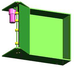
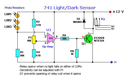
The customer needs, concept generation, concept selection, and prototypes have led to the construction of the beta prototype shown in figure 4 . It was constructed from 0.25 inch thick aluminum by a machinist. It included roller bearings on all of the axles, a stronger motor with gearbox was used, and the device was enclosed within a plastic case for safety. The electrical circuit shown in figure 5 was developed and implemented to automatically feed the labels. The circuit uses 3 LDR sensors to monitor the number of labels peeled. Once all of the labels have been peeled, the sensors allow the motor to advance.
 |
|---|
DISCUSSION
A label dispensing device for a sheet of labels 11 ½ wide is more complicated than smaller width label sheet dispensers due to the larger tension requirements. The larger tension not only requires a larger motor to pull the load which costs more money, but increases the ability of the paper to split due to the high tension. The paper supplied by Wal-Mart has perforations after each label and between the three labels. These perforations lower the amount of tension the sheet can under go.
Applying the tension required to separate the label from the backing has been the challenge in the design process. The tension by sprocket rollers caused too much tension on the sheets sprocket holes and tore them. The fitted guide rails that pressed the paper and provided the tension before the roller provided less and less tension with the increased number of paper reloads. These drawbacks forced the use of friction rollers and a spring loaded roller attached to the casing. The friction rollers evenly distribute the tension to the whole sheet and put no tension on the holes. The spring loaded roller attached to the casing allowed for easier loading and no wear on the device due to loading. When the paper is being reloaded, the casing is unlatched and flipped back. This pulls the roller off of the ramp and allows the person loading the paper to just pull the paper over the ramp and separation roller and feed the paper into the friction rollers. The casing is then placed back over the device and the spring loaded roller places the tension on the paper.