Shoulder-Steered Tricycle
ABSTRACT
Commercially available tricycles for individuals with disabilities are relatively uncommon. Those tricycles that do exist cater toward a broader range of people and therefore do not address the specific needs of an individual. Such vehicles can also become very costly. The aim of this project is to modify an existing tricycle to allow a child with Thrombocytopenia-Absent Radii (TAR) syndrome to independently maneuver the vehicle. Designs for three major systems--steering, mounting/dismounting, and pedaling--were developed and implemented. A final evaluation was performed to assess the credibility of the project.
KEYWORDS
TAR Syndrome, tricycle, steering, four-bar linkage, mounting, dismounting, pedaling
BACKGROUND
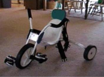
The client is a five year-old child born with TAR syndrome. This particular disorder is characterized by the absence of radii bones in the forearms, leading to shortness in arm length. Our client displayed limited arm movement and rotation as well as minimal strength in his fingers. Both legs also exhibited restricted bend (15° bend in right leg, 90° in left leg) and strength. The request of the client was to modify his current tricycle for use. The original tricycle design advocated the use of long handlebars that extended outwards towards the shoulders of the rider as seen in Image 1. This tricycle also utilized a traditional pedaling system. The client found such handlebars hard to reach and difficult to manipulate during cycling. Mounting and dismounting of the tricycle was also hindered by the handlebar extensions. Given the limited range of motion and strength in both legs, the client found conventional pedaling to be arduous. Such needs of the client were therefore addressed in the modified design of the tricycle.
 |
DESIGN AND DEVELOPMENT
Steering System
Two main designs were considered in the development of the steering system. The first idea was to incorporate into the tricycle a pegged steering wheel, similar to that used to maneuver a boat. Although this design would allow the client to comfortably position his hands and bring the steering system within reach, the client lacked enough strength to grip the pegs and exert such a force on the wheel. A second approach to the steering system design was therefore adopted.
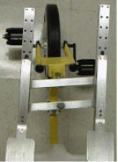 |
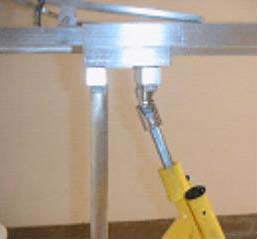
The second design considered was a four-bar linkage, requiring the use of the shoulders for steering. The four-bar linkage consists of two parallel horizontal solid aluminum bars connected to two parallel vertical hollow bars at four pivot points, as seen in Image 2. The first horizontal bar is connected to the front wheel of the tricycle via a universal joint. As Image 3 shows, the connection between the front wheel and the tricycle was angled in the original tricycle design. Since the four-bar linkage steering system must stay parallel to the ground on which the tricycle is sitting, it was necessary to incorporate the universal joint in the design to translate parallel motion of the steering system into angled motion of the wheel. The second horizontal bar is directly attached to the base of the tricycle for support and can freely pivot around its connection point. Both vertical bars are attached to telescoping handlebars that extend toward the client's shoulders. Pushing with the right shoulder will cause the right side of the four-bar linkage to shift forward and the wheel to turn to the left. Similarly, pushing with the left shoulder will cause the tricycle to turn to the right. This particular design capitalizes on the torso strength and flexibility of the client, rather than his arm and finger strength.
 |
Mounting/Dismounting System
By adopting the four-bar linkage design with extended handlebars, the problem of entry and exit of the tricycle still remained. It was thus necessary to design the handlebars that would be able to retract. Two major approaches were developed for this particular system, the first being foldable handlebars. The foldable handlebar design would allow the client to bend the handlebars inward, lock them in place, and in theory, create enough clearance to exit the tricycle. However, due to the small width of the entire steering system, this design was found to provide insufficient clearance. Safety issues with this design were also of concern.
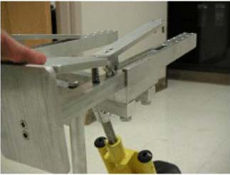 |
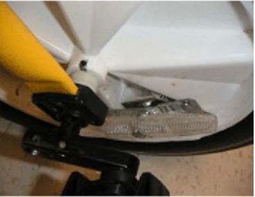
The telescoping handlebar system was developed to address the disadvantages of the foldable handlebars. This particular design utilizes a hollow aluminum tube that is attached to the top of the four-bar linkage and shown in Image 4. Through this tube, a solid bar can telescope in and out to provide enough room for exit. A paddle-bar locking mechanism was then developed to secure the handlebars in place during tricycle use. The paddle-bar is attached to the top surface of the solid telescoping bar via a hinge/spring design and consists on one end of a wide, flat paddle and on the other, two pins. Holes were drilled in the top surface of the hollow aluminum tube into which the paddle-bar pins can drop as seen in Image 1. When exiting the tricycle, the client needs to apply a small force on the paddle to raise the pins and push the handlebars forward. This causes the solid aluminum tube to slide completely into the hollow tube and creates room for the client to independently dismount the tricycle. Conversely, once the client is seated and wishes to begin cycling, the handlebars are pulled towards the client's body and the pins drop into two designated pin holes, locking the handlebars in place. This design not only creates a sufficient amount of clearance for entry and exit, but is also allows for increased adjustability. By drilling several pairs of holes in the hollow tube, the handlebars can then be adjusted to different lengths. The telescoping handlebar design also alleviates any safety concerns that the foldable handlebars raised.
Pedaling System
 |
The initial idea for the pedaling system called for push pedals, such as those seen on a stair-climbing exercise machine. This idea takes advantage of the client's ankle flexion; however, it is an extremely complicated design to implement on a tricycle. Instead, the traditional pedaling system was modified slightly in order to accommodate the limited bend and strength in the client's legs. Through client observation, it was found that the left leg had enough range and bend to pedal but the right leg did not. To address the restricted range of motion for the right leg, the crank shaft of the right pedal was shortened as seen in Image 5. This decreased the effective range through which the right foot would move. Given the minimal strength of the right leg, a weighted wheel was also created to help the forward pedaling motion. Five fishing weights were attached to the wheel slightly off center from the point where the right pedal is positioned at the top of the cycling motion. These weights ultimately created a torque that would force the wheel to turn forward. It also is believed that keeping with the traditional pedaling motion will therapeutically benefit the client by strengthening his leg and hip muscles.
EVALUATION
Each system of the tricycle was assessed separately as well as together. The steering system was evaluated by having the client steer the tricycle in both left and right directions, taking into account ease of use and effectiveness. The mounting/dismounting system was evaluated by observing the client manipulate the telescoping handlebars. Clearance was also noted. An assessment of the pedaling system was made by observing the client pedal on various surfaces. It was found that the client was able to independently manipulate and maneuver all three systems. The entire device was presented to a panel including professors, biomedical engineering students, the client's family, and the client's physical therapist. Feedback and suggestions were provided at the presentation and final modifications were made.
DISCUSSION AND CONCLUSIONS
Prior to the modifications, the client required help in mounting the tricycle, could not reach the handlebars, and had difficulty pedaling the tricycle. The client is now able to independently enter and exit the tricycle, steer, and pedal with relative ease. Several limitations to the design have been observed. The client's turning radius is limitedsince the client has limited range of bend and motion in his legs, the client will be unable to reach the pedals if the wheel is turned too far away. The client also exhibits difficulty in pedaling on carpeted surfaces but is able to smoothly propel the tricycle on the other surfaces. As the client grows and becomes accustomed to the cycling motion, several adjustments can be made to the tricycle. The seat, handlebar length, crank shaft length, and weights on the wheel can all be increased or decreased as the need arises. Overall, the modifications to the three systems allow for future adjustments and ultimately address the client's needs.
ACKNOWLEDGEMENTS
Without the help of Joe Owen, this tricycle would never have been transformed from paper to reality. Our professors, Kevin Caves and Richard Goldberg, provided much assistance throughout the design period. Finally, our client and his family have been wonderful to work with, and made the authors' learning experience especially meaningful.
Author Contact Information:
Irene Tseng,
350 West 43 rd St., Apt. 20D,
New York, NY 10036,
Phone: (919) 451-6977,
EMAIL: irene.tseng@duke.edu