DESIGN OF A MODULAR ASSISTIVE PHOTOGRAPHY DEVICE
ABSTRACT
The driving factor behind the design of assistive technologies is to enable people with disabilities to perform functions that improve their quality of life. While several technologies exist that make daily activities much simpler, one area that receives little attention is leisure and recreation. This paper presents the design of a device that attempts to enable users with limited body movement capability to engage in photography as a recreational activity. This is achieved by providing accessibility through remote switches that enable the user to control the motion of a digital camera and release the shutter to take a picture.
KEYWORDS
Modular; assistive; pan; pitch; automatic
BACKGROUND
The McBeth Recreation Center is a facility funded by the Austin City Parks and Recreation Department that provides a daytime activity center for people with disabilities. Because McBeth is primarily devoted to recreation, most of the activities at the center focus purely on leisure and fun.
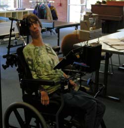
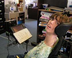
Julie Stewart, our primary customer, is a regular visitor at the center. She is intelligent and loves to interact with people. However, cerebral palsy limits her activities and hobbies. One such hobby is the art and expression of photography. Julie has shown great interest in photography, but is unable to operate a standard camera.
The focus of this design project is the development of an assistive camera aiming and picture-taking device. The design will give Julie the opportunity to take pictures, expanding her range of leisure activities. The product can also be extremely useful to anyone who enjoys photography, but cannot manually operate a camera.
PROBLEM DEFINITION
The process of taking a photograph involves some primary motions of the camera (changing the elevation, pan and tilt) and shutter-release. For a person with limited motor skills it is desirable that most of these motions be automated, requiring minimum input from the user.
The goal of this project was to design and create a device that allowed users with profound disabilities to operate a camera autonomously. This design focused on providing the users with the ability to control the pan motion and the shutter release with the elevation and tilt motion being adjusted by an aide.
DESIGN METHODOLOGY
A customer centric product design methodology proposed by Otto and Wood [1] has been used during the development of this device. The various phases are problem definition, customer needs analysis, functional modeling, concept generation, concept selection and prototyping.
The customer needs were determined from observations of the physical abilities of the primary customer and interviews of her mother, therapists and teachers. A thorough analysis and interpretation of the customer needs helped to translate them into engineering requirements. These were then used to establish a House of Quality by Quality Functional Deployment. The House of Quality illustrates the relationships between requirements and needs, their relative importance and establishes quantifiable target values for engineering specifications.
With these in mind, the next step was concept generation. A functional representation of the whole process was created with modeling of every basic function. This was combined with brainstorming sessions to generate solutions for each function. These different solution principles were combined to form concept variants. The different variants were then evaluated and ranked against each other using criteria (safety, ease of use, manufacturability, size, etc.) drawn from the target specifications .
With the choice narrowed down to a single concept using the rankings, the detailed design process commenced.
A proof of concept prototype was used for the analysis of the design variant. Theoretical (for example finite element models for stress analysis) and experimental models (for example, models of the electronic circuit) were used to refine the concept variant resulting in the alpha prototype, which was then presented to the customer for review. The issues that called for most attention at this stage were the user interface and structural aspects. The insights gained from the alpha prototype and customer feedback were used to rectify the problems associated with the alpha prototype, thereby resulting in the final design of the product, i.e. the beta prototype.
DESIGN EMBODIMENT
 |
The product had to perform two main functions for the user- automatic shutter release of the camera and control of pan motion.
Automatic shutter release is done using a solenoid. On pressing a momentary contact switch, the solenoid is activated and it pushes the camera shutter release button. Pan motion is obtained by connecting a motor to the base of the camera. To obtain the required low speed, a gear box is connected between the supply and the motor. Limit switches are mounted on the extremes of the pan motion range which give the user an appropriate field of vision, in accordance with the visibility of the LCD screen on a digital camera. The direction of motion changes every time the camera hits the limit switches and thus automatic pan motion is obtained. The user can start or stop the motion by using another momentary contact switch.
The final or the beta prototype consists of a black box (i.e. hidden from the user) that houses the entire electronic circuit. The electronics consist of three component circuits -a latching circuit, a motor reversing circuit and a shutter release circuit. The power supply used is a 12V DC battery. The latching circuit provides continuous flow of current when a momentary impulse switch is pressed. The motor reversing circuit consists of relays and limit switches.
 |
The circuit box is placed between two attachment bars that connect to a swing arm attachment mounted on user's wheelchair (This is available as standard equipment and can be mounted on any wheelchair). The top ends of the bars are bent and the camera, solenoid and motor assembly are mounted on this end.
The camera is mounted on a sheet metal frame that completely wraps around the camera. The camera is fixed in a slot at the base of the metal plate with a standard screw usually used for tripod mounting. The primary function of the slot is to enable the frame to accommodate different camera sizes. A hole is drilled at the top of the frame for the entry of the solenoid and it is located exactly above the camera trigger button. The slot allows for the mounting of different sizes of cameras and also allows for adjustment of the horizontal position so that the solenoid is exactly in line with the trigger.
The two momentary contact switches used to control the shutter release and pan motion can be placed at any position convenient to the user. These switches have a large, soft-feel interface for easy use. A separate power switch provides power to the whole device. This switch is controlled by an aide of the user thus preventing accidental start/stop. This allows the device to be used only under supervision.
DESIGN EVALUATION
The device described in this paper is unique in that it allows the customer to explore a whole new leisure activity that may have not been possible without the availability of such a device. The device has been designed keeping in mind the abilities of the end user, who may not be physically able to control a large number of interfaces. The modular nature of the device allows components to be switched out easily during repair or maintenance. The product has been manufactured using mostly off the shelf components, which makes it easily reproducible and at a very reasonable cost. The device is also easily adaptable to different customers by carrying out some minor modifications to the interfaces that should not involve too much effort. The design initially included a DC motor variable speed controller, but in the end we were unable to utilize this as we could not resolve the conflicts between the switching of motor direction and the resulting reversal of current which adversely affected the controller. The speed of the system without additional control is toward the upper limit of usability for our customers, but is acceptable.
DISCUSSION AND CONCLUSIONS
Using a structured engineering design methodology, the authors designed and developed a unique modular assistive photography device to provide a new venue of leisure to people who previously lacked options. Further improvements for the mechanism include incorporation of a speed controller, automatic pitch adjustment, quick-release mounting hardware, and a sturdier mounting frame to reduce vibrations and oscillations resulting from abrupt movements of the base on which the mechanism is mounted.
ACKNOWLEDGMENTS
The authors would like to thank Dr. Kristin Wood and Dr. Rich Crawford of the Department of Mechanical Engineering at the University for providing us an opportunity to work on this project and for their reviews, guidance and motivation. Thanks also go to Amy Collins of McBeth Recreation Center who provided us valuable insights during the development process. The acknowledgements would not be complete without extending our appreciation to our primary customer.
REFERENCE
- K.N. Otto, K.L. Wood, Product Design , Prentice Hall, Inc., NJ, 2001.
Author Contact Information:
Ganesh Krishnamoorthy
Department of Mechanical Engineering,
University of Texas at Austin,
1 University Station, R9925,
Austin, TX-78712-1100
Phone: (512)-471-1626
Email: ganeshk@mail.utexas.edu
