Custom Canes and Brackets
ABSTRACT
Our client was an active woman with osteoarthritis. Her forearm canes were comfortable, but didn't absorb shocks or provide sufficient traction when she walked on trails in the woods. The goal of this project was to modify her canes to provide these features. We integrated commercial spring shock absorbers and flexible traction tips into her canes, which increased each cane's weight by only 3.2 ounces. We also developed a custom system for mounting the canes onto her powered scooter. The custom canes and brackets will reduce strain on our client's shoulders, improve her stability on outdoor walks, and increase her mobility over longer distances. The design has the potential to positively impact the lives of many arthritis patients and other cane users.
KEYWORDS
Osteoarthritis, traction, shock absorption, cane
BACKGROUND
Osteoarthritis affects about 20.7 million Americans, mostly over the age of 45. The condition is characterized by the deterioration of cartilage in the joints. Without the padding of cartilage, an arthritis patient's bones rub against each other, causing pain that ranges from mild to severe (1).
Our client is an active woman who enjoys walking in the woods and on nature trails for recreation. She stands 5'1½ tall. She has severe osteoarthritis and uses Guardian model 5191 forearm canes and a Rascal model 305 scooter in her everyday activities.
Our client's canes were effective on smooth surfaces, both indoors and outdoors, but they posed a safety concern on rough outdoor surfaces, as they tended to slip. Her arthritic shoulders absorbed most of the impact between the canes and the ground, causing significant pain. She also had trouble transporting her canes on her scooter, further limiting her mobility.
Our client had commercial, enlarged rubber tips on her canes to increase contact area with the ground, but was still unsatisfied with her canes' ability to grip rough surfaces. Manufacturers produce models of canes and walking sticks with built-in traction devices on the tips (2, 3,4), but our client was satisfied with her current forearm brace design and did not want to move away from her cane model. The same is true for shock absorption components: commercial canes that include shock absorption exist (5), but no design is adequately similar to her current model of canes. In addition, our client had tried installing commercial mounting devices on her scooter, but she had trouble reaching them and they mounted her canes too high. She wanted to be able to mount her canes in a more convenient location with little effort.
PROBLEM STATEMENT
The main goal of this project was to develop a pair of custom canes and brackets that would increase our client's mobility. Since device failure was our most prominent safety concern, the canes needed to be safe and durable. They also had to be comfortable since she would be using them throughout the day. Other objectives included increasing traction, providing shock absorption, and providing for easy transport on the scooter. Finally, we did not want to add significant weight to our client's canes, to maintain portability and ease of use.
DESIGN AND DEVELOPMENT
 |
We met with our client and supervisor regularly to identify and assess the needs and rationale for the devices and to make adjustments according to their feedback. We left the canes with our client numerous times for a period of days as final adjustments were made so that she could suggest changes as we completed the devices.
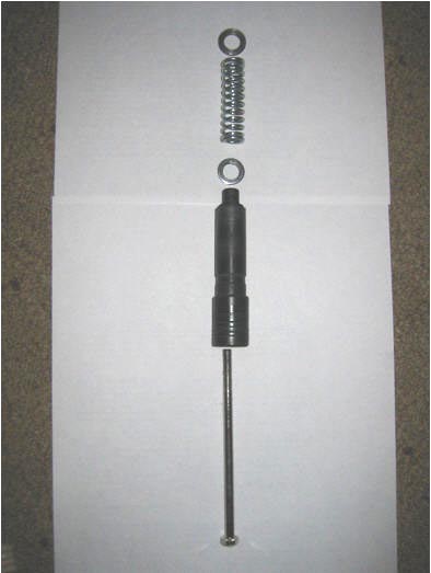
We began with a preliminary design involving four components: canes, traction tips, shock absorbers, and brackets. We found a pair of commercial canes with built-in spring shock absorbers, but using these canes as the main cane shaft was not appropriate because they did not have the forearm components that our client wanted. We therefore removed the spring shock absorbers from these commercial canes and mounted them in our client's canes. The commercial spring shock absorbers were composed of a threaded top stopper, a spring, a long hex screw, and a plastic molding. The canes were smaller in diameter than our client's Guardian cane shafts, so the shock absorbers would not fit directly into the Guardian shafts. We designed a number of parts that were machined to fit the commercial shock absorbers into the Guardian canes (Figure 1).
 |
An aluminum top stopper was affixed with screws into the Guardian shaft, and a plastic sleeve was fit around the molding to increase its diameter so it fit snugly inside the shaft. We also designed custom washers to fit between the top stopper and the spring, as well as between the spring and the molding, to minimize the wearing effects of continuous use. The complete custom shock absorbers fit securely inside the Guardian shafts.
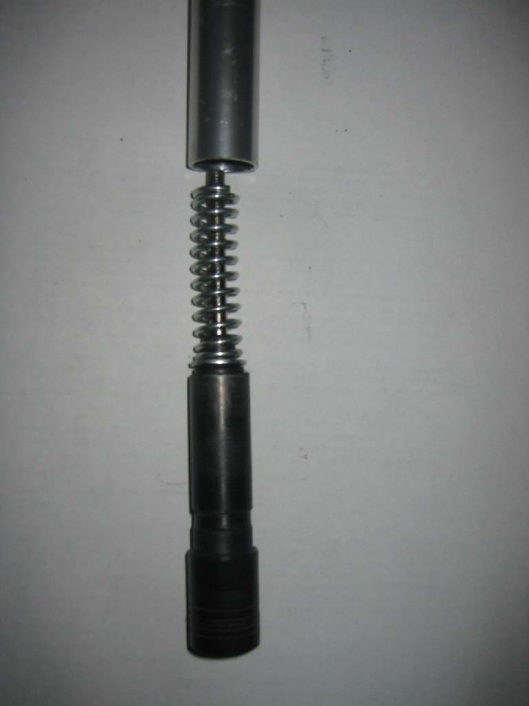
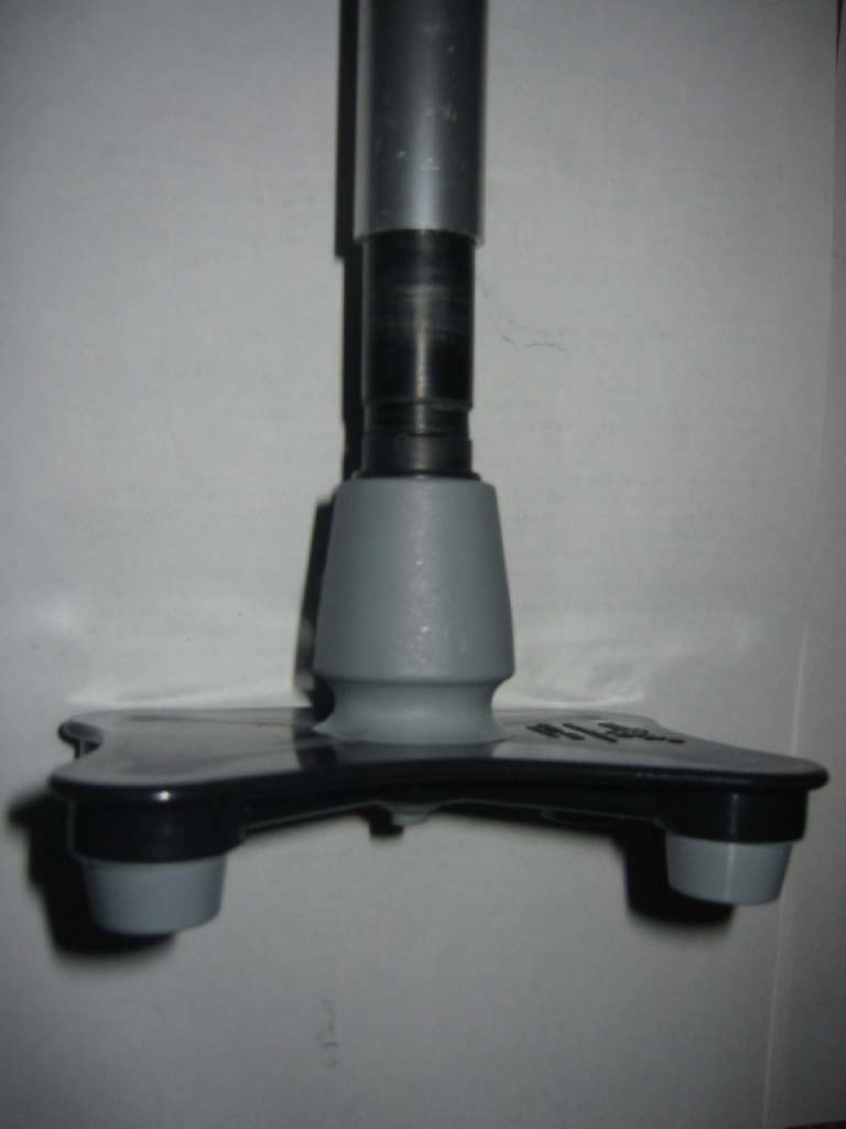
After researching several options for traction tips, including spikes and cleats, we selected the Unifoot (6), which provides a rectangular base with four rubber contact points and a flexible ankle. The Unifoot attaches to the widened tip of the plastic molding portion of the shock absorber. A custom plastic sleeve was machined to ensure a tight fit of the molding inside the Unifoot (Figure 2).
 |
Our client tested the canes with the shock absorbers and Unifoot tips and noticed that the shock absorber continually rotated during use, moving the Unifoot into off-axis positions. To correct this, we added a locking set screw which, once our client had found her ideal level of shock absorption, was screwed through the top stopper and into the long hex screw to stop the system from rotating.
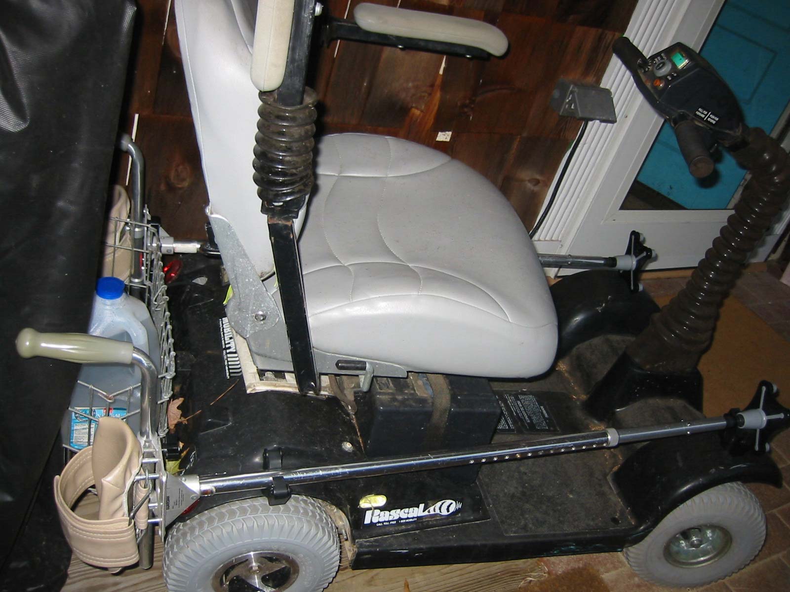
We observed that our client could easily mount and remove her canes if they were mounted parallel to the ground, one on each side of the scooter, resting on the upper surfaces of the scooter's front and back fenders. We attached a commercial bracket called EZGrip (7) on the rear fender and a custom U-shaped guiding bracket on the front fender (Figure 3). Both were secured with screws through aluminum plates, to evenly distribute the screws' forces across the plastic surfaces. Our client mounts the custom canes on her scooter by placing the end of the shaft, just above the Unifoot, in the guiding bracket, then pressing the top of the shaft into the EZGrip bracket. The seat of her scooter rotates so that she can mount one cane on each side of the seat.
 |
EVALUATION
Throughout the design process, we and our client used and evaluated the components and the full canes. We identified problems and made adjustments as necessary. Our most valuable evaluation technique was allowing our client to use the canes at their various stages of completion and offer suggestions and comments. Our client expressed excitement about the completed canes, saying, The shock absorbers have already made such a difference. I already don't think I could go back to the regular canes. They just take the impact so nicely and make my shoulders feel so much better. Being able to mount [the canes] on my scooter will make getting around so much easier, especially when I'm with [a child].
DISCUSSION AND CONCLUSIONS
The components that we added to our client's canes have improved her safety, comfort, and ease of use. In initial testing, the shock absorbers eliminated much of the pain she previously felt in her shoulders. The custom components did not alter the upper portion of the canes, with which she was satisfied, and added only 3.2 ounces to the weight per cane. The brackets on her scooter will allow her to independently transport her canes, which she could not do previously. The devices have the potential to be useful for many active people with arthritis.
The main limitation of the custom shock absorbers is that they were custom made for the client's Guardian canes. However, the design could be applied to a variety of canes, by constructing different parts with diameters matching those of available cane shafts. Also, the mounting placement was developed specifically for our client's scooter model, and may not position the canes conveniently on other models of scooters; however, the brackets adapt to many cane sizes and can be placed in alternate positions on other scooters.
REFERENCES
- Arthritis Foundation. Osteoarthritis. Retrieved September 17, 2003 from http://www.arthritis.org .
- Cane Tips. Retrieved September 15, 2003 from http://www.walkingequipment.com .
- ce Picks. Retrieved September 15, 2003 from http://www.westons.com .
- Trekking Poles. Retrieved September 15, 2003 from http://www.leki.com .
- Trekking Poles. Retrieved September 15, 2003 from http://www.trekkingpoles.com .
- Unifoot. Retrieved September 15, 2003 from http://www.unifoot.com .
- EZGrip Bracket. Retrieved September 16, 2003 from http://www.fashionablecanes.com .
ACKNOWLEDGMENTS
We would like to thank Dr. Larry Bohs, our professor, and Mark Palmeri, our Teaching Assistant for valuable guidance and assistance with this project. We thank Joe Owen for machining all of our custom designed parts. Finally, we would like to thank our client and project supervisor, Christina Lomax, for helping us with our device design and identification of problems. This material is based upon work supported by the National Science Foundation under Grant No. 0118558.
Author Contact Information:
Lindsay Boole
2204 Countrywood North Rd.
Raleigh, NC 27615
Email: lcb8@duke.edu