Removal of Dynamic Offset Signal from Load Cell Instrumented Wheels
ABSTRACT
One method that has been used to measure the forces and moments applied to the handrim during manual wheelchair propulsion is a load cell instrumented test wheel. The attachment of a handrim to an instrumented test wheel with a pre-calibrated load cell introduces a dynamic offset signal. As the wheel rotates, the load cell coordinate system also rotates, resulting in a dynamic offset due to the weight of the handrim. This study investigated a method to remove the dynamic offset signal by recording offset data for the load cell/handrim assemblies prior to having the test subject push the wheelchair. Offset splines relative to wheel angle position were measured, averaged, and subtracted from the propulsion data. The results of this study showed the feasibility of this method. Dynamic offset signal can be easily removed using this technique for a variety of attached handrim assemblies, without the time and expense of recalibrating the load cell.
KEYWORDS
Dynamic offset, biomechanics, load cell, wheelchair propulsion, propulsiometer
BACKGROUND
As researchers attempt to better understand manual wheelchair propulsion, the accurate collection of handrim force and moment data during the push is essential. One of the methods that have been used to measure the forces and moments applied to the handrim is a load cell instrumented test wheel [1,2]. With a load cell instrumented wheel, the handrim is coupled to the wheel through a six-degree of freedom load cell. The load cell measures forces and moments in 3 axes. Load cells are pre-calibrated by the manufacturer. The load cell output is converted into handrim force and moment values using the load cell calibration matrix provided by the manufacturer.
Each force is measured with respect to the load cell's local coordinate system. When a handrim is attached to the load cell, its weight influences the load cell measurement. As the wheel rotates, the load cell coordinate system also rotates, resulting in an oscillatory dynamic offset. While the primary effect of the dynamic offset can be removed by subtracting the handrim weight vector as the wheel rotates, there are other effects such as dynamic imbalance and the variations in weight between different handrim assemblies which complicate the offset removal process.
RESEARCH QUESTION
Can the dynamic offset signal from load cell instrumented wheels be removed by simply subtracting an experimentally measured offset vector from the load cell measurements?
METHOD
A 30-year-old male, full-time manual wheelchair user, with a level T-12 spinal cord injury and seven years of wheelchair experience, participated in this study. The subject's 24 inch rear wheels were replaced with test wheels. The right test wheel was equipped with a commercially available load cell (ATI, Garner, NC) to measure the forces and moments applied to an attached handrim assembly, and an absolute inclinometer (US Digital, Vancouver, WA) to measure the wheel angle. Signals from the wheel sensors were sampled wirelessly via a MiniDat (ViaSat, Carlsbad, CA) by a data acquisition system at 400 Hz (National Instruments, Austin, TX).
 |
|---|
The subject was positioned on a treadmill, and his wheelchair was attached to the front of the treadmill using a tether. The treadmill was then set to a 2% uphill grade with a velocity of 0.94 m/s (2.1 mph). The test subject sat with his hands in his lap while the tether held the wheelchair stationary on the treadmill. Dynamic offset data were collected during the first 5 wheel revolutions. The subject was then asked to complete a total of 40 pushes. Load cell measurements were then smoothed using a low pass, fourth order, Butterworth filter, with a cutoff frequency of 20 Hz.
Dynamic offset data for the first five wheel rotations were independently isolated. Offset vectors with respect to wheel angle were created for each rotation. These offset vectors were used to generate 0-359 degree splines. An ensemble average of the five separate splines was performed to create a single offset vector. This averaged dynamic offset vector was then used to correct the recorded force and moment data.
RESULTS
 |
|---|
Although dynamic offset results were recorded for the load cell in all six degrees of freedom, the x and y components of force were determined to be the most influenced by wheel rotation. The x and y components of the averaged dynamic offset vector were oscillatory in nature. The average values of both dynamic offset components were shifted away from zero, indicating that static offset components were also present (Figure 1). As expected, the subtraction of the averaged offset vector from the force results of the first five wheel revolutions returned the x and y component values to zero.
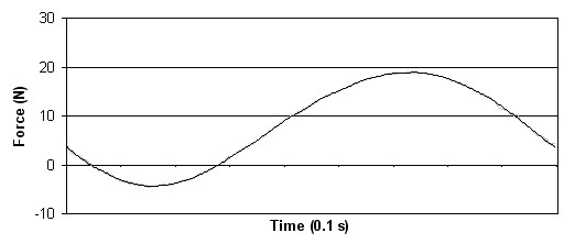
The resulting horizontal handrim force applied during propulsion, after the removal of offset, returned to zero between pushes regardless of the rotational position of the wheel (Figure 2). The force was converted from the load cell's coordinate system to an inertial reference frame. The x component, and specifically the peak force, is now truly representative of the applied handrim force only. Similar results were found for the y force component.
DISCUSSION
The five single rotation Fx offset spines along with the averaged spline are shown graphed on top of one another (Figure 3). It can be seen that they are very consistent. This consistency suggests that dynamic offset data for a single wheel rotation may be sufficient for creating an acceptable 0-359 degree offset spline.
 |
|---|
This dynamic offset removal technique is easy to apply. The method used demonstrates an effective way for manual wheelchair propulsion researchers to remove dynamic offset signal from load cell instrumented test wheels. Also, the use of dynamic offset removal allows the researcher to compensate for a variety of handrims with different weights and mass distributions, without the time and expense of recalibrating the load cell. This method would allow research using other types of instrumented wheels, such as the SMARTWheel (Three Rivers, Mesa, AZ), to remove dynamic offset. If a dynamometer is used rather than a treadmill, the dynamometer could be driven at the target velocity prior to propulsion data collection.
It must be noted that this research was conducted at constant velocity in a clinical environment. In addition, the dynamic offset vector does not compensate for any inertial loading due to wheelchair accelerations or decelerations, such as would occur while traveling across rough terrain. Further research is needed to determine if the dynamic offset vector is velocity dependent. If the effect is not dependent upon velocity, free spinning the test wheel may be a feasible way to generate a dynamic offset vector.
REFERENCES
- Sabick MB, Zhao KD, Kai-Nan A (2001). A comparison of methods to compute the point of force application in handrim wheelchair propulsion: a technical note. Journal of Rehabilitation Research and Development , 38(1): 57-68.
- Richter WM, Axelson P (2003). Effect of a vinyl-coated handrim on wheelchair use. Proceedings of the American Society of Biomechanics Conference, ASB Conference, Toledo, OH
ACKNOWLEDGMENTS
This research was funded by the National Center for Medical Rehabilitation Research in the National Institute of Child Health and Human Development at the National Institutes of Health through Small Business Innovation Research Phase II Grant #2 R44 HD36533-02A2. Additional support was provided by the College of Engineering, Technology and Computer Science at Tennessee State University.
Kevin R. Woods
kwoods03@mytsu.tnstate.edu
Nashville, TN
(615) 837-6902