Christopher A. Schafer, Joseph Zaworski, Michael J. Pavol
National Center for Accessible Transportation, Oregon State University, Corvallis, OR
Abstract
Transfers onboard an aircraft are a major source of injury during air travel by people with disabilities. These risks might be reduced through biomechanical study of the transfer task. Such study requires that the contact forces acting on the body during a transfer be known, including the contact force between the rear transferor and the seatback. A seatback-mounted force plate was constructed that is capable of accurately measuring the total normal contact force magnitude and the center of pressure of this applied force. By allowing the measurement of forces that may have otherwise been ignored, the seatback-mounted force plate can greatly improve the quality of biomechanical analyses of transfers.
KEYWORDS: force plate, transfer, biomechanics
Introduction
People who use a wheelchair due to a disability are particularly afflicted by barriers to air transportation. While the Air Carrier Access Act of 1990 (1) ensures that people are not prohibited from flying based on their disability, many wheelchair users either cannot or choose not to travel by air due to accessibility issues. One major concern related to air travel by people with disabilities is the transfer between the aisle chair and seat onboard an aircraft. These transfers are a major source of injury to travelers with disabilities, and to the airline personnel who assist in dependent transfers.
The current industry standard for dependent transfers onboard an aircraft is the two-person front/back technique. In this technique, one transferor reaches beneath the arms of the passenger and grasps the wrists from behind while the other transferor grasps just proximal to the knee from in front. As a team, the transferors lift the passenger from the aisle chair into the aircraft seat. Such transfers pose a special difficulty due to the spatial confines onboard the aircraft. In particular, the transferor to the rear must reach over the back of the aisle chair and seat. This awkward lifting posture increases the risk that the passenger will be moved roughly or dropped, as well as the risk of low back injury to the transferor.
To address these risks, we are researching the biomechanics of dependent transfers onboard an aircraft. We hypothesize that the risks of injury to both passengers and transferors may be reduced through interventions that reduce the forces and moments at the joints of the transferors during a transfer. To estimate these joint kinetics, it is necessary to know all of the external contact forces acting distal to the joint of interest. Floor-mounted force plates exist to measure the forces between the feet and ground, however video recordings of transfers also showed substantial contact between the rear transferor and the seatback. The forces associated with this contact must be measured and included in the biomechanical analyses. This paper presents a seatback-mounted force plate that we developed for this purpose.
Design Requirements
 |
Visual analysis of the transfer video recordings indicated that only one body segment distal to the lumbar spine contacted the seatback during the period of primary interest: the transferor’s inboard thigh. Contact occurred at the knee and/or lower edge of the tray table and appeared to be mainly compressive in nature. The seatback force plate thus had to be able to measure the total compressive force being applied normal to the seatback in the area between the lower edge of the tray table and the knee height of a 5% female. The force plate also had to allow the center of pressure of the applied force to be determined. Based upon a model-predicted maximum static loading of 660 N, and assuming that the load could triple under dynamic conditions, a measuring capacity of approximately 2000 N was needed. Dimensionally, the device had to fit unobtrusively within the seatback volume and to simulate the original seatback geometry in areas of transferor contact. These requirements placed rigid constraints on the device’s external dimensions: width: 349 mm; height: 318 mm; maximum depth: 41.4 mm. Finally, the force plate had to be easily interfaced to and synchronized with a motion capture system sampling at 600 Hz.
Design
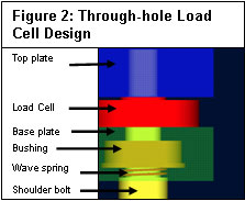 |
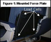
The force plate employs four compression-type load cells (Futek 2760, Irvine, CA) mounted between two 12.7mm aluminum plates, one load cell near each corner of the force plate, giving a capacity of 2224 N (Fig 1). Noise or damage due to shear loading is minimized by using through-hole load cells and passing bolts from the top plate, through the load cells, into bushings in the base plate (Fig 2). Past each bushing, a spring applies a constant force to the bolt head to hold the plates together and apply a preload force to the load cell. With this design, shear forces are effectively transferred to the bolts, while normal forces are applied to the load cell and measured. In addition, the preload keeps the load cells in compression should small tensile loads be applied due to torsion, mounting the force plate in an inclined position, or applying loads outside the area included by the load cells. The base plate of the force plate mounts directly to the right and left rails of the seat frame. An aluminum channel mounted to the top plate simulates the tray table edge. For interfacing to a motion capture system, each load cell is connected to an amplifier (Sensotec UV-10, Columbus, OH) that converts the measured force to a 0-10V analog signal.
 |
The total normal force applied to the force plate is computed by summing the forces measured by the four load cells. The location of the center of pressure is computed such that the moment about the force plate origin due to the total normal force acting at the center of pressure equals the sum of the moments due to the forces measured by the four load cells (Fig 3). We have defined the origin to be at the lower left corner of the top plate.
Testing
Calibration coefficients (N/V) for the four load cells were determined through multiple linear regression of 186 data points corresponding to loads of 0, 111, 222, 334, and 445 N applied at a grid of nine locations on the force plate. The mean magnitude of the residuals from the regression was used to assess measurement accuracy for an applied normal force. Measurement accuracy of the center of pressure was tested by using a custom fixture to apply a concentrated 222 N load at the same nine known grid locations on the force plate, with 32 data points collected. The frequency response of the force plate was determined through application of an impulse to the center of the plate and using optimization to fit the plate’s dynamic force vs. time response to the sum of a second-order underdamped oscillation and an exponential decay. The resulting natural frequency of the oscillations was averaged across 8 trials.
RESULTS
The force plate met all of the design requirements and the measurement errors for the applied normal force and center of pressure were well within acceptable limits (Table 1). The identified natural frequency of 352Hz is comparable to commercially available force plates.
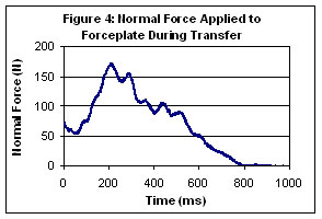 |
Sample data collected from the force plate during a dependent transfer in our laboratory illustrate that considerable contact forces may act between the rear transferor and the seatback during the transfer (Fig 4). Peak normal contact forces between the transferor and seatback in our pilot data have typically been in the range of 80 to 180 N, which is well within the capacity of the force plate.
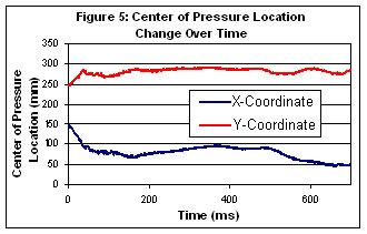
Initial results from the center of pressure calculations have also been as expected. In most cases, the center of pressure of the contact force between the rear transferor and the seatback during a dependent transfer into a seat to the right of the aisle is located in the upper left region of the plate (Fig 5). Contact of the transferor’s right knee with this area of the seat has frequently been observed in our pilot data.
 |
Discussion
The seatback force plate that has been developed is capable of very accurately measuring the magnitude and location of dynamic normal forces applied to its surface. Its use will enable more accurate biomechanical modeling of the task of a dependent transfer onboard an aircraft by allowing the contact forces between the rear transferor and the seatback to be included in the computation of joint forces and moments. Furthermore, the careful integration of the force plate into the geometry of the seat should result in minimal impact on the behaviors of the experimental subjects.
There are some limitations to the force plate. First, due to the inherent flexibility of the lightweight airplane seat, torsional loads are often applied to the force plate. Our testing indicates that, with its four-load cell design, the force plate can tolerate considerable torsion with minimal effect. However, extreme cases will cause inaccurate measurement. Second, in developing the device’s engineering requirements, the shear force applied to the seatback by the transferor was deemed negligible. If nontrivial shear forces are in fact present, some degree of inaccuracy will be introduced, as these forces will not be measured.
This force plate allows biomechanics researchers to capture the normal forces occurring between an experimental subject and an airplane seatback during a dependent transfer. This is a significant advance over previous research on transfers, in which contact forces other than those with the ground have been neglected. The inclusion of these seatback forces will create a superior biomechanical model and yield more accurate results. Force plates of similar design could arguably be created for other environments, including wheelchair-to-bed transfers and wheelchair-to-toilet transfers, yielding comparable positive outcomes that may ultimately lead to safer transfers for people with disabilities.
REFERENCES
- Nondiscrimination on the Basis of Disability in Air Travel. Title 14, Volume 4, Parts 200 to 1199. U.S. Code of Federal Regulations, Sec. 382. Revised as of January 1, 1999.
ACKNOWLEDGEMENTS
Funded through grant H133E030009 from the U.S. Dept. of Education, National Institute of Disability and Rehabilitation Research
CONTACT :
Chris Schafer
204 Rogers Hall
Oregon State Univ.
Corvallis, OR 97331.
(503) 789-4711