Erica L. Authier B.S.1, Sarah Wyszomierski1, Emily Zipfel BFA1, Jeremy Puhlman B.S.1, Songfeng Guo Ph.D.1, Rory Cooper Ph.D.1, Edmund F. LoPresti Ph.D.2, Rich Simpson Ph.D.1
1Departments of Rehabilitation Science and Technology, and Bioengineering, University of Pittsburgh, Pittsburgh, PA; 2AT Sciences, Pittsburgh, PA 15213
ABSTRACT
The Smart Power Assistance Module is being developed to meet the mobility needs of those members of the wheelchair-user population who cannot safely drive their chairs without assistance. The current phase of research focuses on the design and fabrication of an advanced level prototype that is suitable for user testing and continued experimentation. The current prototype includes multiple sensor modality housings and mounting hardware.
KEYWORDS:
independent mobility, power assistance, modularity, rehabilitation robotics, wheelchairs
BACKGROUND
Independent mobility plays an important role in the prevention of physical and emotional difficulties experienced by individuals with disabilities (1). “Smart Wheelchairs” have been created to accommodate persons who find operating a standard power wheelchair difficult or impossible. Such difficulty is often due to multiple disabilities, such as low vision, visual field neglect, spasticity, tremors, or cognitive deficits, for example. About 7,544,000 people in the U.S have both a physical and sensory (speech, hearing, vision) disability, while 4,294,000 people have a combination of physical, perceptual, and mental disabilities (2). Previous smart wheelchairs utilized existing technology developed for mobile robots and typically consisted of either a standard power wheelchair base in combination with a computer and an array of sensors or a seat attached to a mobile robot base. The setup of these systems required wheelchair modification that may interfere with service delivery, client seating, and other needs.
The Smart Wheelchair Component System (SWCS) was developed as a modular alternative to existing smart wheelchairs (3). Developed for power wheelchairs, the SWCS consists of an array of sonar and infrared sensors placed strategically around the perimeter of the chair, control electronics, computational hardware, navigation assistance software, and rear and front bumpers, and requires minimal modification of the user’s wheelchair. The Smart Power Assistance Module (SPAM) is a navigation module adapted for manual wheelchairs, which combines the latest version of the SWCS and Yamaha JWII Power Assist Wheelchair Hubs (4-5). The SWCS technology has been transferred to manual wheelchairs in the hopes of providing a mobility solution for populations with either visual or cognitive and physical impairments.
STATEMENT OF PROBLEM
The first generation hardware SPAM was developed to provide a proof of concept prototype (5). This phase of the design focuses on the development of a second generation SPAM prototype that is both suitable for user testing and flexible enough for further experimentation purposes.
RATIONALE
Mechanical components of SPAM include: sensor modules, lap bar, back bar, clamps, front bumpers, rear bumper, electronics box and mounting hardware, and JWII wheels. Design requirements compiled by the design team included requirements for the end user as well as the electronic developers. The requirements developed to meet end user needs included: attractiveness, usability, portability, modularity, safety, and minimal maintenance requirements. The requirements developed to meet the needs of the electronics developers included: modularity, flexibility, modifiability, protection of electronics, allow for electronics development, suitability for laboratory testing, and functionality.
DESIGN
 |
|---|
 |
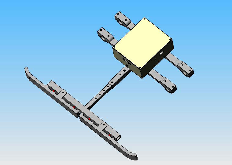
The redesign of the SPAM prototype began with the electronics box and mounting hardware (see figure 1 left). The electronics box was designed to be slightly oversized to both house the new electronics board and provide ample space to allow for further development. Slots for the attachment of specified connectors were designed into the box to allow for connector securement and strain relief. The mounting hardware consisted of two separate beams that clamp to the base of the wheelchair, and was designed to attach the box to a wheelchair at a point that would interfere the least with wheelchair use.
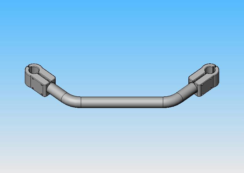
The front bumpers, located on the footrests of the wheelchair (figure 1 right), and rear bumpers (figure 1 left), located behind the wheels at a height near the center of the wheels, allow the chair to detect an obstacle prior to a collision between the chair and the obstacle. This feature is a “last resort” for obstacle detection if long-range sensors fail. The rear bumper interfaces with the electronics mounting hardware through a base of hollow nested tubing. The nested tubing will hide the wire path, as well as make the bumper adjustable for use on a variety of chairs. Solid aluminum covered with plastic or foam to absorb impact will be used for the actual bumper. The two bumper pieces use pivot points combined with four switches to provide maximum detection and flexibility. Head-on collisions with an object will be detected by the inner switches, while collision at an angle will activate the outer switches. Stops will be added to prevent jam of the bumper and switches. To ensure maximum obstacle detection and protection of the chair and the user, the bumper spans the chair width, curving around the wheel to prevent snagging of an obstacle. The front bumpers are designed with the same features.
 |
|---|
 |
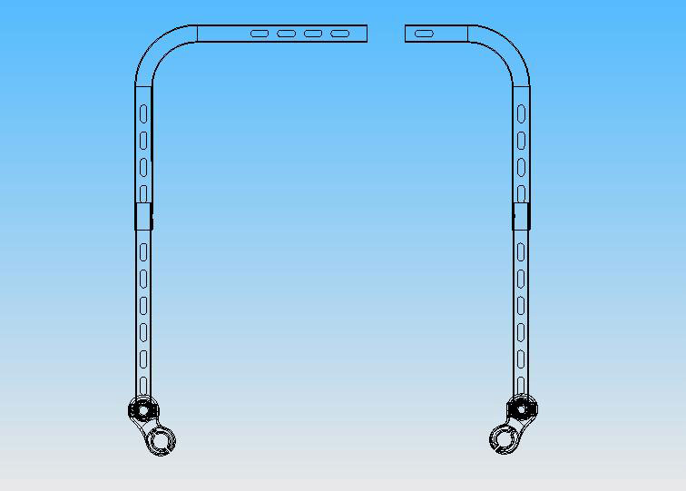
The front and back bars of the SPAM provide a means of arrangement and attachment for the sensor modules around the chair (figure 2). There are five important features of the lap bar including a front plug that allows for securement and easy opening of the lap bar, the use of tubing to house the electrical cables, slots on the bottom of the tube to allow for sensor positioning all along lap bar, telescoping tubing that allows the dimensions of the bar to be fit to any wheelchair and a clamp that allows for 180 degree rotation of the two sides of the bar. The back bar was designed to firmly attach to the chair behind the back rest and was also designed with slots along the length of the bar for flexibility in the placement of the sensors. The sensor modules were redesigned to provide more flexibility, adjustability, and multiple sensor configurations during testing as well as better durability and crashworthiness. In addition, the new design brings the prototype closer to what SPAM sensor modules may look like as a consumer product (6).
DEVELOPMENT
The design process for all parts included 3D modeling in Solid Works TM or FeatureCam TM prior to fabrication. Figure one is the Solid Works 3D model of the new SWCS designed for the second generation SPAM. Aluminum was the chosen material for most of the parts because it is both lightweight and strong. The front bars of the lap bar and the back bar were fabricated out of 1 inch aluminum tubing, first bent at 90 degree angles and then milled on a milling machine (vendor location). The side bars were fabricated out of 7/8 inch aluminum tubing and slots were milled into the bars. Clamps for the bars were first cut on a Wire EDM machine and then milled. The clamps for the back bar were split before drilling and tapping. The sensor modules and electronics housing were built on a Stereolithography (SLA) machine. The clamps for the mounting hardware for the electronics box were fabricated using Wire EDM and the beams were machined on a manual mill. The electronics housing was then mounted to the beams using Velcro. The rear bumper, not yet fabricated, will be milled using aluminum to make the hardware lightweight, flexible, and durable.
EVALUATION
 |
|---|
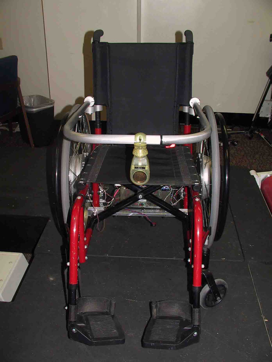 |
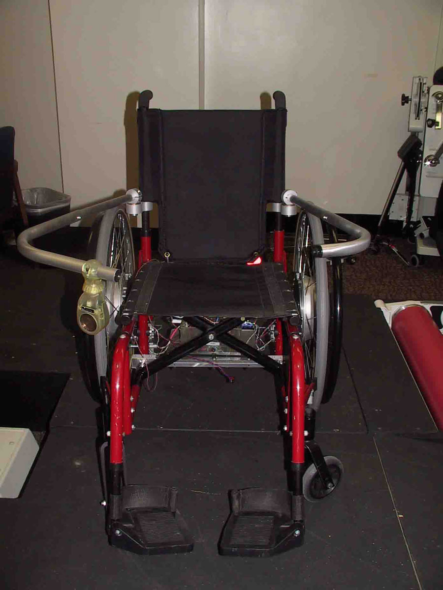
The fabricated components, along with SWCS electronics and power assist wheels, were mounted on a Quickie 2 (Sunrise Medical, CA) (figure 3). Although the design criteria were met, modifications were identified for the next iteration. The electronics box design will likely be made smaller due to the high cost of SLA resin and bulk of the current design. A different material, such as aluminum or plastic, may be used to alleviate this cost and avoid the brittleness of SLA resin, thus providing more durability. Waterproofing and electromagnetic interference will also be considered. The simple design of the mounting hardware was easy to mill and assemble, and the location beneath the seat prevented interference with other system components and maintained the balance of the chair. Future mounting hardware will utilize nested tubing to allow the system the adjustability to fit a variety of chair widths and a base to secure the housing. The lap and back bars provide the adjustability, strength, and usability identified as necessary in the requirements. Testing will determine the best sensor configurations, therefore future designs will likely require less adjustability. Future sensor modules will be manufactured using a Selective Laser Sintering machine which is capable of building parts in aluminum and a wider variety of plastics.
DISCUSSION
The rear and front bumpers are in the process of being fabricated and have not yet been evaluated. Future work includes the continued fabrication and redesign of components and laboratory testing. This final iteration will produce a consumer product prototype that will be appropriate in clinical subject testing.
REFERENCES
- L. Iezzoni, E. McCarthy, R. Davis, and H. Siebens. Mobility difficulties are not only a problem of old age. Journal of General Internal Medicine, 2001, 16: 235-243.
- J. McNeil. Americans with disabilities: 1997, 1997. Current Population Reports P70-73.
- Simpson, R., LoPresti, E., Hayashi, S., Nourbakhsh, I., Miller, D. (2004). The Smart Wheelchair Component System. Journal of Rehabilitation Research and Development. 41(3B):429-442.
- Simpson, R., LoPresti, E., Hayashi, S., Guo, S., Ding, D., Cooper, R. Smart Power Assistance Module for Manual Wheelchairs. Proceedings of the RESNA 2003 Annual Conference. June 2003.
- Frisch, R.F., Guo S., Cooper R., LoPresti E.F., Simpson R., Hayashi S., Ammer W. Hardware Design of the Smart Power Assistance Module for Manual Wheelchairs. Proceedings of the RESNA 2004 Annual Conference. June 2004.
- Zipfel, E., Cooper R., Authier E.L., LoPresti E.F., Puhlman J., Simpson R., Wyszomierski S. A Novel Sensor Housing Design for the Smart Power Assistance Module (SPAM). Proceedings of the RESNA 2005 Annual Conference. In Press.
ACKNOWLEDGEMENTS
This work was supported by the National Institutes of Health (1R43 EY 014490-01) and the University of Pittsburgh Bioengineering Department. Special thanks are extended to the Human Engineering Research Laboratories.
Author Contact Information:
Erica L. Authier, BS
Human Engineering Research Laboratories
VA Pittsburgh Healthcare System
7180 Highland Dr, 151R-1
Pittsburgh, PA 15206
Phone 412-365-4850
Email authiere@herlpitt.org