29th Annual RESNA Conference Proceedings
Using Miniature Data Loggers to Characterize Electric Powered Wheelchair Performance
Donald M. Spaeth, PhD, RET; Karl W. Brown, BSAE; Rory A. Cooper, PhD
Human Engineering Research Laboratories, Pittsburgh VA Healthcare System, Pittsburgh PA
KEYWORDS:
Odometry, vehicle tracking, wheelchair controls,
ABSTRACT
Verifying improved control of electric mobility requires tracking electric powered wheelchair (EPW) motion and characterizing the ballistic response of the power train. In prior studies, Optitrack, Vicon and video recording equipment have been successfully used. Imaging instrumentation has limitations. Multiple cameras, interface electronics and computers are needed and markers must be placed on the wheelchair frame and the system carefully calibrated. The complexity of these systems usually requires dedicated laboratory space and considerable investigator skill. This paper reports an alternative method for recording wheelchair motion by using a pair of HERL's miniature data loggers (MDL). MDLs are self-contained motion recorders that record a "time stamp" after each 120 degrees of rotation. When used with three inch diameter casters, the sampling rate is approximately 30 Hertz at chair speeds of 6 miles per hour. Comparing the velocities of the left and right MDLs allows the wheelchair path to be recreated over short distances. A working prototype of this hardware is being test to improve the realism of a wheelchair driving simulator. Plans for improving this device are presented.
BACKGROUND
Electric powered wheelchairs not only provide mobility but are a significant determinant of employment and community participation Approximately 2.2 million Americans living in community settings use wheeled mobility device. About ten-percent of these individuals use electric power wheelchairs (EPWs) or scooters [1] . In 2000, Fehr et al [2] estimated between 25 and 50% of individuals who sought powered mobility could not be fitted because their perceptual and motor disorders precluded safe wheelchair driving. Based on these sources, it is estimated that there is a hidden population of some 200,000+ non driving individuals who could potentially be aided by improved EPW controls.
The Human Engineering Research Laboratories (HERL) has an ongoing research mission of developing improved control interfaces that will enfranchise individuals with severe movement disorders that cannot drive with commercial joysticks. [3-5] . Several on going studies make use of a virtual EPW driving simulator to provide a safe environment for subject testing with the added benefit of background data recording. To be authentic, the simulator software needs accurate ballistic parameters about the consumer's personal EPW. A few manufacturers publish performance specifications, but usually programmable features are listed as percentages of the maximum available and not actually quantified. In prior studies HERL investigators used tracking systems such as OptiTrack ( Corvallis, OR) , Vicon (Oxford, UK) and a mobile camcorder [6] . All of these imaging methods require cameras, data acquisition cards and computers to record data. With fixed location cameras, the chair must have markers at least one of which is always in the visual field of at least two cameras. If the cameras are mobile, then the floor must have markings. Spaeth [7] in his doctorial dissertation avoided the requirement for path recording by instead measuring target acquisition time which under the Fitts' law model is a well accepted indicator of movement skill. Spaeth's study still required a mobile computer and optical sensors to detect when the chair was over the target. In addition to cost and setup time, the complexity of these systems usually requires dedicated laboratory space and considerable investigator skill.
An alternative to imaging instruments is to place shaft encoders on or parallel to the EPW drive wheels and record the movement changes across time. Determining a vehicle's position and heading without external references is commonly called "dead reckoning" and in the field of robotics, "Odometry". Odometry is subject to more sources of error than fixed reference tracking; the most obvious being wheel slippage and skidding. [8] More subtle errors are introduced through certain simplifying assumptions e.g. that wheels make contact at the center of their tread width. Optical encoders record in finite rotational steps and velocity changes between steps are interpolated. Depending on the conversion algorithm chosen, errors can accumulate and must either be corrected in software or cleared by periodic updating with an external reference. Odometry was chosen here because it can vastly reduce instrumentation overhead making it practical to characterize a consumer's personal EPW. EPW ballistic features are mostly brief events; i.e. rate of acceleration, top speed, turning rate.
METHOD
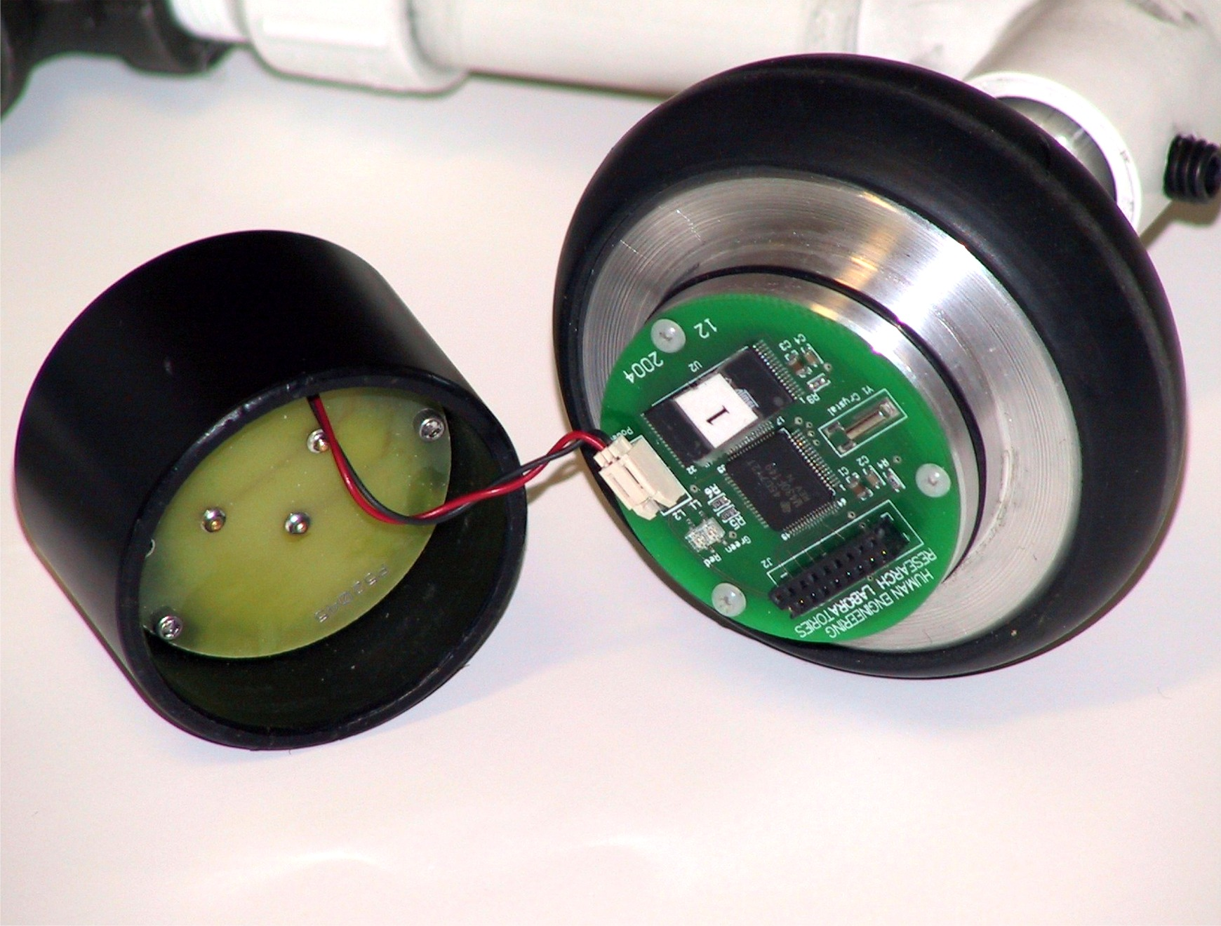 Figure 1. (Click image for larger view)
 We used two HERL miniature data loggers (MDL) which have proven successful for recording wheelchair daily activity [9] . The MDL is a self contained motion recorder containing a pendulum, three reed switches and an embedded microcontroller with flash memory. [10] Typically, the MDL is mounted on a 24 inch manual wheelchair wheel and as it rotates, a small magnet on the pendulum sweeps over the reed switches generating three digital pulses per revolution. Each pulse results in a "timestamp" being added to the flash memory. Various data compression strategies allow up to seven hundred miles of activity to be recorded on the 32 megabit memory chip.
 Figure 2. (Click image for larger view)
 To create an odometry instrument, two MDLs were mounted on three inch diameter casters. The casters were arranged on a frame so that they can be positioned parallel to the drive axis of a wheelchair.
Figure 1 and Figure 2 are close up views of the data logger modules. Figure two shows the PC board removed; note that the pendulum has been removed and the magnet is now mounted on a stationary arm. The entire data logger module rotates about the arm as the EPW is driven. Figure 3 illustrates the final instrument positioned between the drive wheels of our test chair.
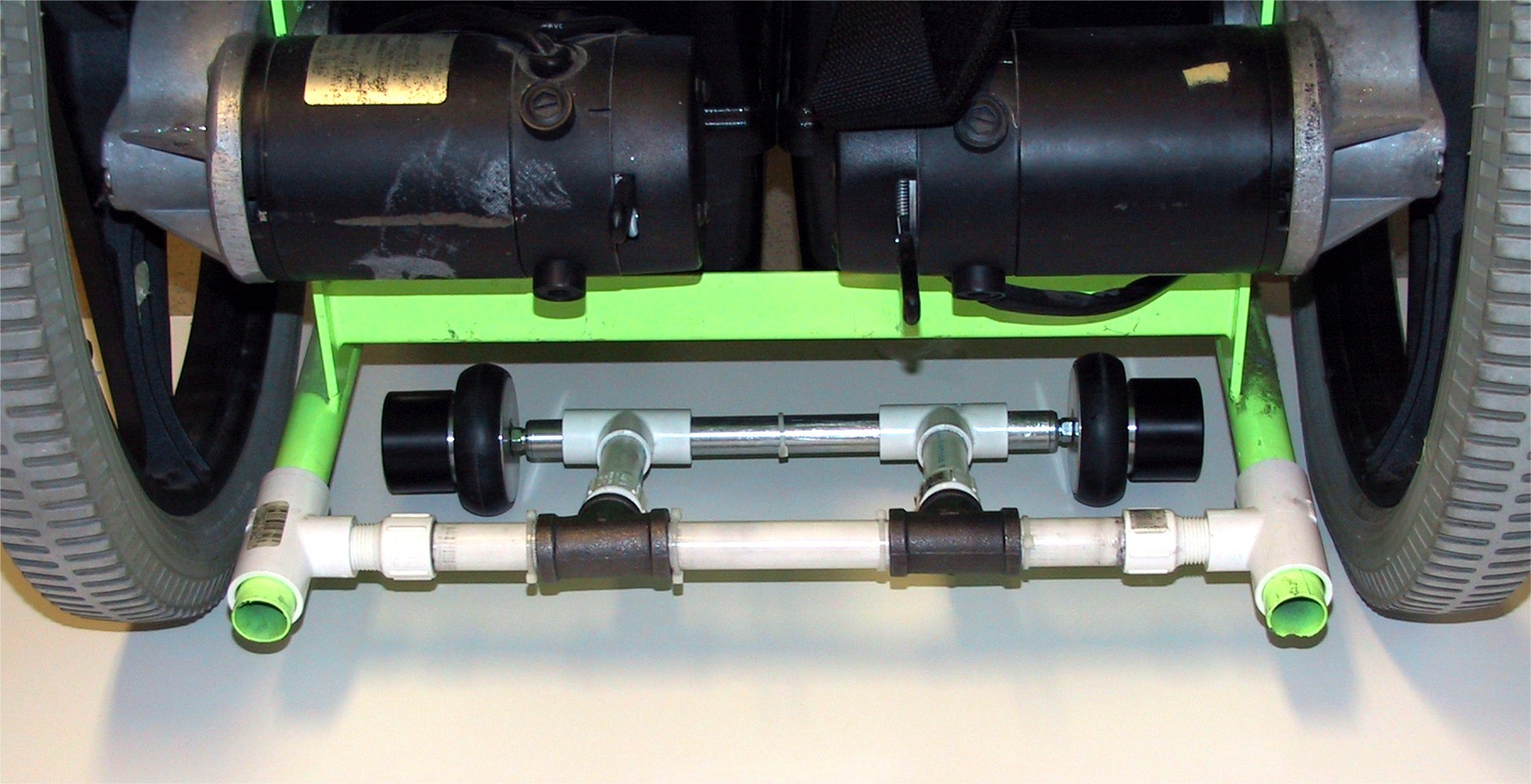 Figure 3. (Click image for larger view)
At six miles per hour, the three inch diameters MDLs generate 30 updates per second at approximately three inch intervals. The embedded software for the MDL's real-time clock was reworked to increase the time resolution from 0.1 seconds to .001 seconds. The timestamp format was increased from 8 to 16 bits.
RESULTS
Table 1 is a sample of raw data from a forward acceleration test.
| Left | Right | |||||||
|---|---|---|---|---|---|---|---|---|
| Sensor | Minutes | Seconds | msecs | Sensor | Minutes | Seconds | msecs | |
| 9 | S3 |
0 |
1 |
115 |
S1 |
1 |
55 |
793 |
| 10 | S1 |
0 |
21 |
943 |
S3 |
0 |
0 |
606 |
| 11 | S2 |
0 |
1 |
900 |
S2 |
0 |
0 |
239 |
| 12 | S3 |
0 |
0 |
328 |
S1 |
0 |
0 |
183 |
| 13 | S1 |
0 |
0 |
680 |
S3 |
0 |
0 |
179 |
| 14 | S2 |
0 |
0 |
435 |
S2 |
0 |
0 |
151 |
| 15 | S1 |
0 |
25 |
103 |
S1 |
0 |
0 |
167 |
| 16 | S3 |
0 |
46 |
295 |
S3 |
0 |
0 |
178 |
| 17 | S1 |
1 |
39 |
483 |
S2 |
0 |
0 |
144 |
| 18 | S2 |
0 |
12 |
388 |
S1 |
0 |
0 |
139 |
| 19 | S3 |
0 |
9 |
47 |
S3 |
0 |
0 |
140 |
| 20 | S1 |
1 |
46 |
743 |
S2 |
0 |
0 |
91 |
| 21 | S2 |
0 |
0 |
380 |
S1 |
0 |
0 |
86 |
| 22 | S3 |
0 |
0 |
220 |
S3 |
0 |
0 |
82 |
| 23 | S1 |
0 |
0 |
159 |
S2 |
0 |
0 |
64 |
| 24 | S2 |
0 |
0 |
171 |
Si |
0 |
0 |
65 |
| 25 | S3 |
0 |
0 |
169 |
S3 |
0 |
0 |
66 |
| 26 | Si |
0 |
0 |
149 |
S2 |
0 |
0 |
56 |
| 27 | S2 |
0 |
0 |
165 |
S1 |
0 |
0 |
59 |
| 28 | S3 |
0 |
0 |
140 |
S3 |
0 |
0 |
62 |
| 29 | S1 |
0 |
0 |
102 |
S2 |
0 |
0 |
52 |
| 30 | S2 |
0 |
0 |
101 |
S1 |
0 |
0 |
55 |
| 31 | S3 |
0 |
0 |
89 |
S3 |
0 |
0 |
60 |
| 32 | Si |
0 |
0 |
70 |
S2 |
0 |
0 |
50 |
| 33 | S2 |
0 |
0 |
75 |
S1 |
0 |
0 |
53 |
| 34 | S3 |
0 |
0 |
71 |
S3 |
0 |
0 |
57 |
| 35 | S1 |
0 |
0 |
59 |
S2 |
0 |
0 |
47 |
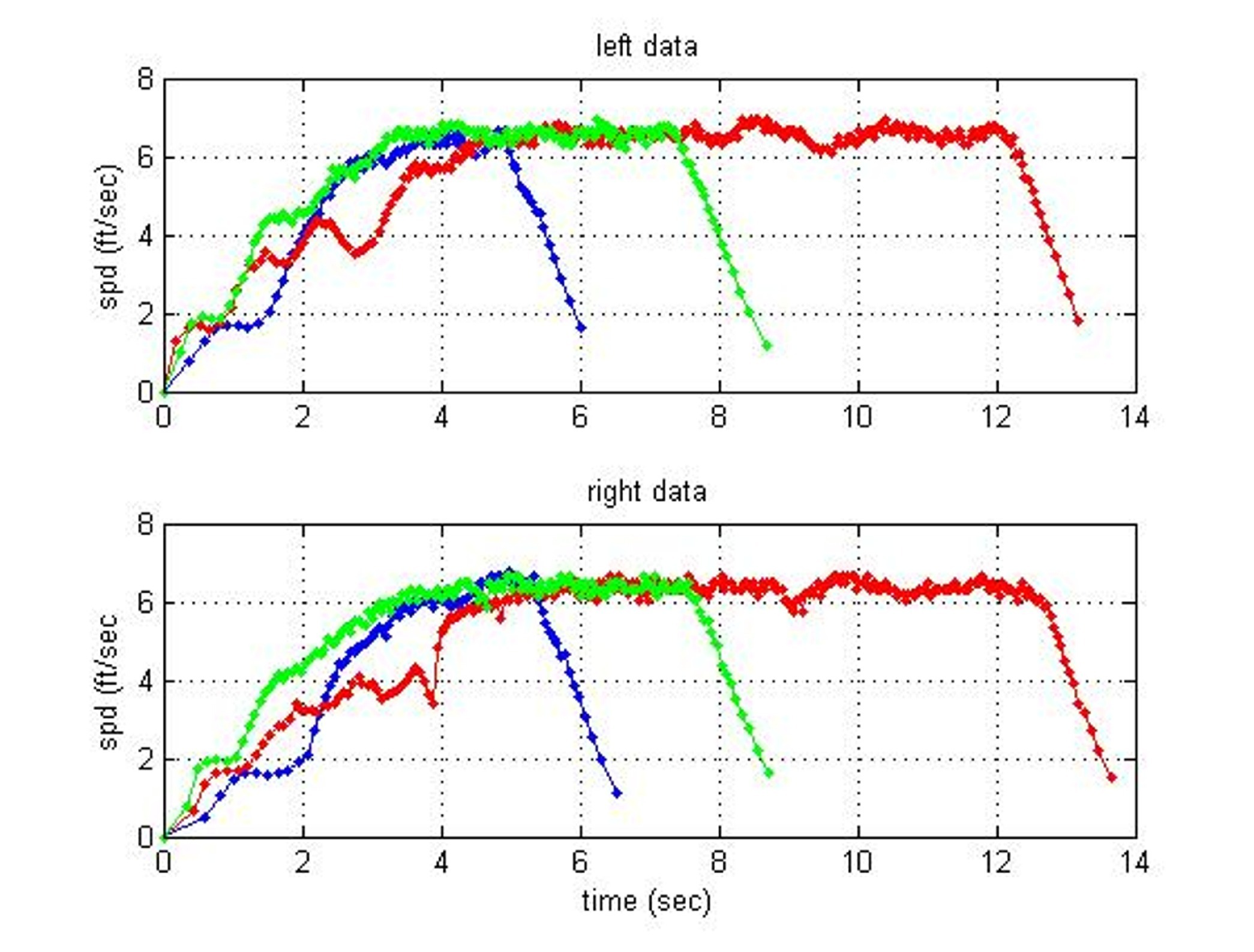 Figure 4. (Click image for larger view)
 The records from the two data loggers are arranged side by side. All time values are deltas (elapsed time from the previous event). The separate data loggers can be synchronized by identifying a string of fractional second events that follow a record of several minutes.. The reader will note the decreasing size of the deltas (indicating increasing velocity). Also note that the sensor sequences occur in reverse order on the second device. Figure 4 is a graph illustrating four trials of forward acceleration.
The joystick was initially applied to the maximum forward position and held until speed stabilized and then stick was released. Note the rapid rate of deceleration due to the action of the wheel brakes.
DISCUSSION
The initial results are promising. Figure 4 indicates that the chair consistently required about four seconds attaining full speed. The under carriage mounting frame worked well on our test chair. Other EPWs with low ground clearance will require outboard encoder mounting. A different hardware configuration using a single data logger CPU linked to two optical encoders would simplify the data collection and support higher sampling rates. To fully define wheelchair driving parameters, the joystick input must also be recorded concurrently with encoder data.
REFERENCES
- Kaye, HS, Kang, T, and Laplante, MP(2000). Disability Statistics Report - Mobility Device use in the United States, US Department of Education, National Institute of Disability and Rehabilitation Research. Washington, DC
- Fehr L, Langbein E, and Skaar SB, "Adequacy of power wheelchair control interfaces for persons with severe disabilities: A clinical survey," Journal of Rehabilitation Research and Development, vol. 37 pp. 353-360, 2000.
- Cooper RA, Widman LM, Jones DK, and Robertson RN, "Force Sensing Control for Electric Powered Wheelchairs," IEEE Transactions on Control Systems Technology, vol. 8 pp. 112-117, 2000.
- Cooper RA, Jones DK, Fitzgerald S, Boninger ML, and Albright SJ, "Analysis of position and isometric joysticks for powered wheelchair driving," IEEE Transactions on Biomedical Engineering, vol. 47, no. 7, pp. 902-910, 2000.
- Cooper RA, Spaeth DM, Jones DK et al, "Comparison of virtual and real electric powered wheelchair driving using a position sensing joystick and an isometric joystick," Medical Engineering and Physics, vol. 24 pp. 703-708, 2002.
- Jones DK, Cooper RA, Albright S, and DiGiovine M, "Powered wheelchair driving performance using force and position-sensing joysticks" 24th Annual Northeast Bioengineering Conference, 1998.
- Spaeth, DM, "Evaluation of an isometric joystick with control enhancing algorithms for improved driving of electric powered wheelchairs." Doctoral Dissertation, Department of Rehabilitation Science and Technology, University of Pittsburgh, 2002.
- Borenstein J and Feng L, "Measurement and correction of systematic odometry errors in mobile robots," IEEE Transactions on Robotics and Automation, vol. 12, no. 6, pp. 869-880, 1996.
- Cooper RA, Thorman T, Cooper R et al, "Driving characteristics of electric powered wheelchairs: how far, fast and often do people drive?," Archives of Physical Medicine and Rehabilitation, vol. 83, no. 2, 2002.
- Spaeth DM, Cooper RA, Albright S, Ammer W, and Puhlman J, "Development of a Miniature Data Logger for Collecting Outcome Measures for Wheeled Mobility" Conference Proceedings RESNA Annual Conference, Orlando, Florida, 2004.
Donald M. Spaeth, PhD, RET
412-365-4850
This should be in the right column.