A Position Concordant Tactile Mouse
Ravi Rastogi, Dianne Pawluk, PhD
ABSTRACT
Tactile mice, computer mice modified to have a tactile display, have been developed to enable access to computer graphics by individuals who are blind or visually impaired. However, current tactile mice (i.e., the VTPlayer) are problematic as there is a mismatch between the location of the position sensor on the mouse used to determine the location of the information on the computer screen to display, and the actual tactile display location. This mismatch is particularly confusing when the user rotates the mouse, as the same information is displayed on the tactile display invariant of the rotation angle. To solve this problem we used: (1) an angle sensor to determine the angular displacement of the mouse, and (2) a mathematical transformation to determine the real screen location of the information to be displayed on the tactile pins. This is expected to eliminate the confusion experienced by users and improve performance.
KEYWORDS
Tactile mouse, Tactile pins, Angle sensor, VTPlayer.
STATEMENT OF PROBLEM
Tactile mice, which consist of computer mice modified to have a tactile display of a matrix of pins that raise and lower (Figure 1a), have often been proposed to enable access to graphical information found on a computer by individuals who are blind or visually impaired. These devices have the potential to be more effective than currently used static methods (such as puff-paper raised line drawings and Braille embosser diagrams) in that they are much more interactive, cheaper and more portable, without wearing as easily. In spite of this, the only tactile mouse that is commercially available is the VTPlayer developed by VirTouch LTD (Jerusalem, Israel) which consists of an optical mouse with two four by four matrices of pins. The two matrices are aligned to sit under the index and middle finger with a normal grasp of the mouse by either hand. The VT Player works by sensing its x-y position through its mouse sensor, as usual. It then displays the binary image information at the corresponding location on the computer screen on the tactile display (figure 1a).
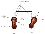 Figure.1 Tactile Mouse d (Click for larger view)
 However, although tactile mice are potentially very useful and the VT Player has been frequently used by the research community (e.g. (1) and (2)), it has yet to really be adapted by the community of people who are blind or visually impaired (in contrast to the more inconvenient static methods). This suggests that there may be a fundamental problem with the VT Player, and tactile mice in general, that limits its acceptance. We suggest that this has to do with the lack of position concordance between the optical sensor sensing the position of the cursor and the feedback provided from the picture. This results from two issues: (1) the mouse being a relative rather than an absolute measuring device (which is relatively easy to fix), and (2) the mismatch between the optical sensor location and the position of the matrix of tactile pins (Figure 1a). The latter results in angular movements of the mouse about the optical sensor location not being accounted for: the same tactile information is displayed independent of the angular movement (Figure 1b) as the optical sensor location is the same. This is not a theoretical point as this was also observed in practice by Jansson and Juhasz (3) while doing their study on reading virtual maps with a haptic mouse. They determined it to be a major factor in confusing the user. In this paper, a solution to this problem of position inaccuracy due to angle displacement of the VT Player is suggested.
APPROACH
 Figure 2: Modified Tactile Mouse d (Click for larger view)
 Two potential solutions to the problem were considered. The first was to move the position of the optical sensor underneath that of the tactile pins to decrease the position mismatch. However, this solution was unsatisfactory as, depending on the angle of rotation, it does not decrease the error sufficiently for all pins, while increasing the physical height of the mouse to an uncomfortable level for the user. The second solution was to measure the angular rotation of the mouse in real world coordinates (Figure 2) and use a mathematical transform (Equation 1) to accurately predict the location of the matrices on the computer screen (Figure.2b).
Equation 1: Determination of coordinate position of a given pin
(X![]() 3,Y
3,Y![]() 3) = (X
3) = (X![]() 1 + R sin (
1 + R sin (![]() δ +
δ + ![]() θ),Y
θ),Y![]() 1 + R cos (
1 + R cos (![]() δ +
δ + ![]() θ))
θ))
Here, (X![]() 3,Y
3,Y![]() 3) is the new coordinate position of a given pin, R is the radial distance between the pin’s position and the optical sensor,
3) is the new coordinate position of a given pin, R is the radial distance between the pin’s position and the optical sensor, ![]() δ is the angular position of the pin from the midline, and
δ is the angular position of the pin from the midline, and ![]() θ is the angular displacement of the midline with respect to the calibrated starting position.
θ is the angular displacement of the midline with respect to the calibrated starting position.
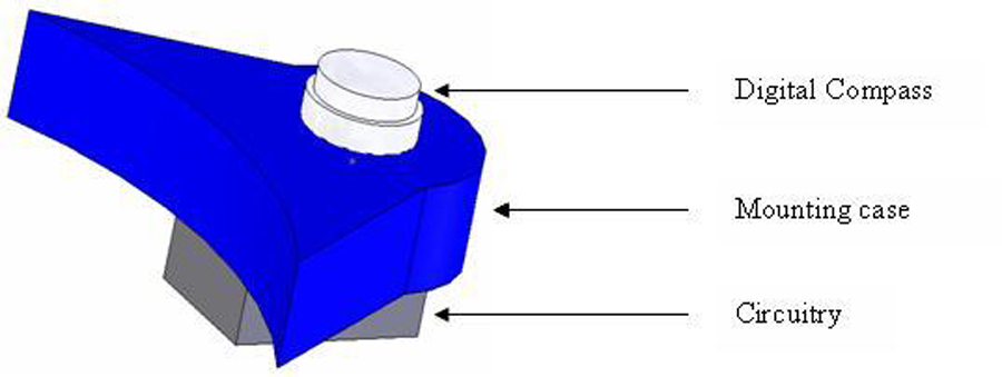 Figure 3: Compass Sensor Mount (Click for larger view)
 For this latter solution several different methods could be used to determine the angular rotation, for instance: (1) the direct measurement of the angle with an analog compass sensor and (2) the measurement of a second (x,y) location, such as through a second optical mouse circuit, to determine the angle of the mouse through mathematical transformations. As direct measurement of the angle of rotation is more straightforward, we chose to use a cost effective Dinsmore R1655 analog compass sensor ($20) to determine the angle of rotation, from which we can calculate the (x,y) position of the pin. This sensor has a two channel output with a 90 degree phase difference between channels, both of which are used to determine the angular rotation of the sensor within their (approximately) linear region. The sensor can be mounted on the front part of the mouse to determine the angular displacement of the midline (Figure 4).
EVALUATION
Before using the Dinsmore sensor to determine the angle for our mathematical transformation, we performed initial testing to check the sufficiency of the sensor by evaluating its hysteresis and repeatability over time.
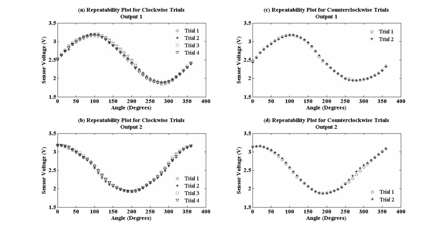
Figure 4: Repeatability testing plot (clockwise and counterclockwise) d
The sensors was tested for repeatability and hysteresis by performing four sets of readings in the clockwise direction, followed by two sets of readings in the counterclockwise direction. During these trials we took readings from the sensor at every ten degree interval starting from zero degrees to three hundred and sixty degrees for the clockwise trials, and three hundred and sixty to zero degrees for the counter clockwise direction. Readings for two of the four clockwise trials were taken at time intervals of 5 minutes to check repeatability over a realistic time usage duration. the data points of the other sets were taken at intervals of approximately 30 seconds each. We found that the sensor characteristics were repeatable in both the clockwise direction and counterclockwise direction (figure3).
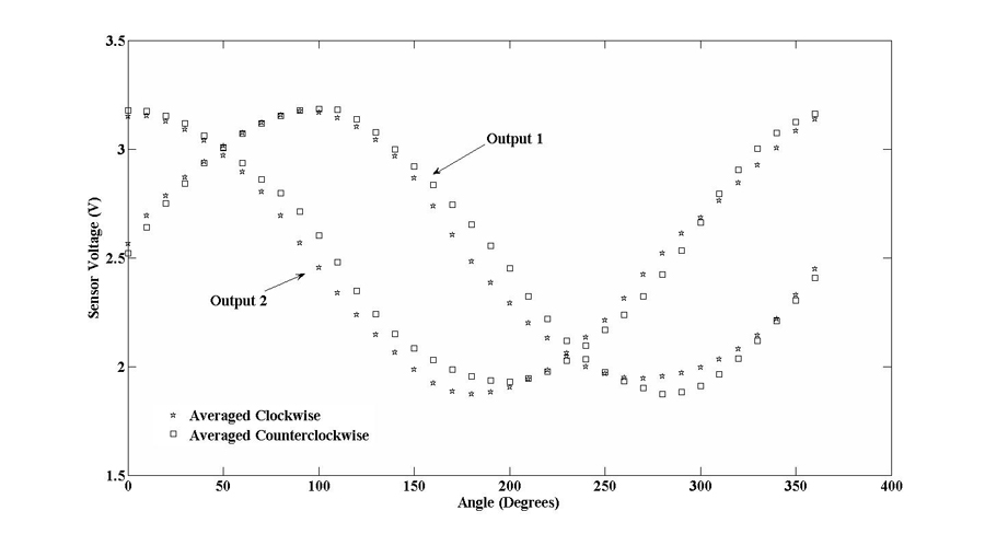
Figure 5: Hysteresis testing plot. (Click for larger view)
Hysteresis did exist for all sensors (figure 7), however, each curve (clockwise or counterclockwise) was fortunately repeatable independent of how many rotations were made before reversing direction and where the reversal took place.
Because of this consistency, the two outputs of the sensor could be used to predict the angular displacement of the sensor. Third degree polynomial equations were fitted to the approximately linear portion of the curves for each output. An algorithm was used to choose which sensor output and which curve (i.e., clockwise or counterclockwise) should be used to calculate the angle of rotation. Our testing of the algorithm accurately predicted any angular displacement of the mouse to within two degrees, with an average error of 0.9123 degree.
IMPLICATIONS AND NEXT STEPS
The average angle accuracy that was obtained was approximately 1 degree. To determine whether this is sufficiently accurate, we need to compare the resulting position error to the tactile acuity of the fingertip. Knowing that the radial distance, R, of the pins from the optical sensor is approximately 8-9cm, and considering the rotation of the hand within the range of 0 to 30 degrees, the Cartesian accuracy of the location of the pins is: 1.2-1.6mm in the x direction and 0-0.7mm in the y direction. This is reasonably acceptable in consideration of the pin spacing of the VT Player (i.e., 2mm), except at larger errors of 2 degrees (producing an error of 3.1mm around 0 degrees in the x direction). However, spatial acuity can be achieved with the VT Player with movement of the mouse as well as spacing of the pins. It is therefore more appropriate to compare the accuracy of this sensor to the spatial resolution of the human tactile system, which is 1mm (4), and the ability to tactually localize a point in space, which is 0.1mm (5). Note that to display a tactile resolution of 1mm, assuming the Nyquist frequency, would require a position accuracy of the pins of 0.5mm.
Another confounding problem is that the settling time of the sensor is around 500 msec. This delay must be added to the 200 msec delay of the VTPlayer to produce a pin movement. This is considerably slower than natural hand movements. Although with slow hand movements, the use of the Dinsmore sensor shows that the method proposed can correct, to a degree, the mismatch between the optical sensor and the pin location, we feel it is still not accurate enough for normal usage by individuals who are blind and visually impaired.
Unfortunately other angle sensors that we have investigated are much higher in cost without any increase in angular accuracy (although some have a faster settling time). Therefore, the next step is to examine the use of sensors that can be used to measure a second (x,y) location. With two positions on the mouse known in real world coordinates, the angle of the mouse can be determined accurately. Two alternate technologies will be considered: optical sensors (such as used in mice) and EMR technology (such as used in tablets). Both are expected to provide more than sufficient position accuracy, although the EMR technology may be too slow for the intended purposes.
ACKNOWLEGEMENTS
This work was supported in part by funding from the Whitaker Foundation and from NSF IIS grant #0712936.
REFERENCE
- Nicolas Noble and Benoit Martin P.(2006), Shape discovering using tactile guidance, Eurohaptics 2006, Paris, France.
- Thomas Pietrazak, Isabelle Pecci and Benoit Martin P.(2006), Satatic and dynamic tactile directional cue experiments with VTPlayer mouse, EuroHaptics 2006, Paris, France..
- Gunnar Jansson, Imer Juhasz, Arina Cammilton, P.(2006). Reading virtual maps with a haptic mouse: Effects of some modifications of the tactile and audio-tactile information. The British Journal of Visual Impairment, 24 (2), 60-66 .
- Kenneth O. Johnson and John R. Phillips, P.(1981), Tactile Spatial Resolution I. Two-Point Discrimination, Gap Detection, Grating Resolution, and Letter Recognition, Journal of Neurophysiology, 46 (6), 1177-1192.
- Jack M. Loomis. (1979). An Investigation of Tactile Hyperacuity. Sensory Processes. (3), 289-302.
Author Contact Information
Ravi Rastogi, Dept of Biomedical Engineering, Virginia Commonwealth University, 701 W Grace Street, Laurel Street Entrance, P.O. Box 843067 | Richmond, Virginia 23284-3067.
Email: rastogir@vcu.edu