The Automatic Rocker
Anne Marie Amacher, Katie Myers and Meredith Cantrell
Duke University, Durham, NC 27708
ABSTRACT
The Hilltop Home in Raleigh, NC is a residential facility for young children with profound physical and mental disabilities. The children enjoy and medically benefit from rhythmic motion, such as rocking, but due to various disabilities, many of these children cannot rock themselves in a standard rocking chair. The automatic rocker we designed and built will allow the children to experience physical stimulation from the rocking motion itself, as well as cognitive stimulation via additional custom features. The design incorporates a glider-style rocking chair powered by an electric gear motor and features such as a timer, child-operable switch, and speed control. The automatic rocker will enrich and diversify the children’s daily routine while reducing time constraints placed on the staff members.
KEYWORDS:
automatic rocking chair, vestibular stimulation
BACKGROUND
In 1960 Wake County civic groups founded the Hilltop Home in Raleigh, NC to address medical and educational needs of children with profound disabilities. Most of the children are non-ambulatory, and many deal with respiratory problems, oral-motor dysfunction, and neuromuscular impairments.
Children enjoy and medically benefit from rocking in a rocking chair, which provides vestibular stimulation. Vestibular stimulation–the body’s perception of motion–can increase alertness, improve reflexes and motor skills, and induce calming in children with disabilities (1,2). Most of the children at the Hilltop Home cannot rock themselves; thus, a staff member is needed to push them. For medical and practical reasons, the Hilltop Home asked us to create an automatic rocker that could safely provide the children with vestibular and cognitive stimulation while minimizing the dependence on staff members.
Students at Utah State University designed an automatic glider rocker for their university’s Center for Persons with Disabilities. The functional specifications of this design call for a smooth continuous rocking motion, variable speed control, an easily accessible control mechanism, and a stationary, self-contained structure (3). Because this design has a wide range of target users, it allows for only limited customization. Our rocker specifically caters to the children at the Hilltop Home via additional support for small children, child-controls, and slow rocking speeds.
PROBLEM STATEMENT
This project’s goal was to create a device that allows children with profound disabilities to experience motion and to develop their abilities through physical and cognitive stimulation. Important objectives included accommodation of children up to 80 lbs in medium or large Tumble FormsÒ feeder seats, use of a child-controllable button to operate movement, adaptability to each child’s physical and mental capabilities, ease of operation for the staff, enjoyment for the children, and safety.
DESIGN AND DEVELOPMENT
 Fig. 1: Moveable Arm System (Click for larger view)
 Our original design plan was to motorize a rocking chair by utilizing a moveable arm system that translates the rotational motion of a gear motor into the translational motion of the chair. We started our design with the Classic Glider Rocker by Storkcraft (model #002646350). We initially built a wooden prototype of the moveable arm system, which verified our design concept. For the prototype we varied the lengths of the fixed and moveable arms to determine the optimal dimensions of these pieces. The moveable arm was affixed to the rocker’s existing wooden moveable dowel with cable ties.
We determined that the motor should supply at least 180 in-lbs of torque to rock an 80 pound child. To meet this specification, we chose a 90 volt DC gear motor by Dayton (model #2H577) that provides 235 in-lbs of torque. This motor operates at a maximum speed of 62 rpm. The rotation of the motor translates into the rocking motion of the chair via the moveable arm system.
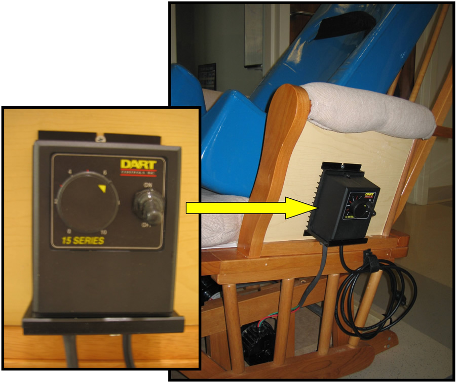 Fig. 2: Speed Control (Click for larger view)
 The fixed arm, moveable arm, and moveable rod comprise the moveable arm system (Photo 1). In the final project, these pieces are made of aluminum. The fixed arm is attached to the motor shaft with two perpendicular screws. The moveable arm is attached to this moveable rod with a press-fit steel ball bearing. The moveable arm is secured to the fixed arm with a pin bearing.
Once the moveable arm system was working, we began focusing on the additional features requested by our client. The speed control by Dart (model #5JJ58) allows users to adjust the speed of the motor within a 0-30 rpm range. One rotation of the motor translates into one full swing of the chair, so the maximum rocking frequency of the chair is one swing every two seconds. The speed control is conveniently mounted on the side of the chair and plugs into a wall outlet (Photo 2)
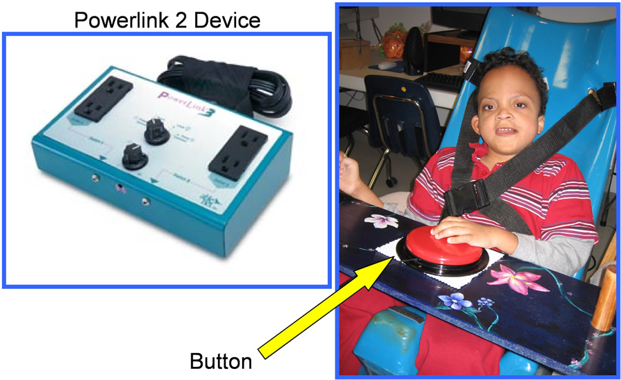 Fig. 3: Powerlink2 (Click for larger view)
 An additional feature is a child-operated button that allows the children to initiate the rocking motion. The PowerLink2 device (AbleNet, Inc.) provides this feature (Photo 3). When the teacher sets the PowerLink2 on either the seconds or minutes timer function, the child must press a button to activate the chair. After the allotted time set by the teacher, the chair automatically stops. The child must first recognize that the rocking motion has stopped and then press the button to reinitiate the rocking motion. Because not all the children have the physical or mental ability to use this feature, the PowerLink2 also has a setting that allows the teacher to turn the device on indefinitely.
We constructed an adjustable desk that holds the child-operable button used with the Powerlink2 device. Two wooden dowels connected to the chair slide through holes in the desk. Two pins fit through holes in the dowels to support the desk at four different heights. (Photo 4).
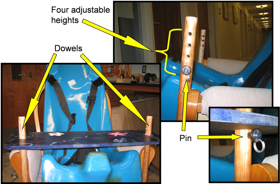 Fig. 4: Desk (Click for larger view)
 The children sit in one of the Tumble Forms seats while rocking. The child seat is secured to the rocking chair with two Velcro straps that fit through slits on the child seat and wrap around the back of the chair (Photo 5). To accommodate all the children, the angle of incline of the child seat is adjustable.
Wheels attached to the back legs of the chair and a lifting strap attached to the front legs (Photo 6) make the chair transportable between classrooms at the Hilltop Home. Lifting the strap upwards tilts the chair back onto the wheels so it can be rolled into an adjacent room.
EVALUATION
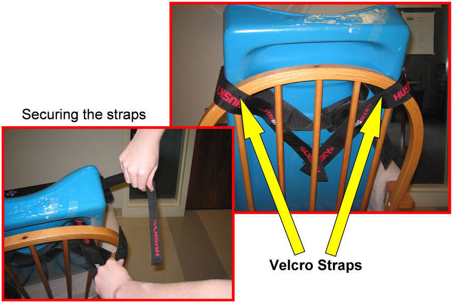 Fig. 5: Child Seat (Click for larger view)
 We can evaluate the success of the Automatic Rocker based on how it cognitively and physically stimulates children at the Hilltop Home. We utilized the Powerlink2 interface with one of the children. The chair was set to rock for 10 seconds after which the boy had to press the button to start rocking again. With each iteration the boy required less time to press the button. This process with the Powerlink2 reinforces cause and effect. The Automatic Rocker also works well in physically stimulating the Hilltop Home children. The speed control provides a range of speeds to accommodate a range of needs. We tested various speeds on four different children. Each child had a different optimal speed at which we could see they felt most comfortable. While rocking, one boy, whom teachers say has trouble holding his head up, worked especially hard to hold his head steady. Teachers recognized one boy had particular improvement in head and neck control while rocking in the chair.
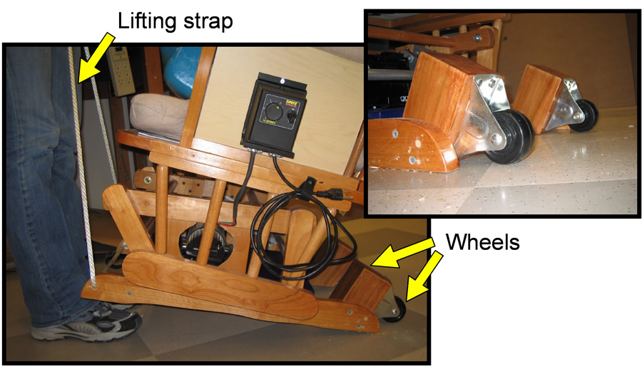 Fig. 6: Mobility System (Click for larger view)
 One unforeseen drawback we discovered upon testing the chair with more weight was that the rocking motion became increasingly more uneven with weights larger than 40-lbs. Rocking was faster in the back-swing of the cycle than the front-swing due to the chair’s natural frequency exerting a large torque in the same direction as that supplied by the motor. This behavior was also observed in a quantitative analysis (Appendix C). During our testing at the Hilltop Home, teachers noticed this effect; however, they said the irregularity did not upset the children but rather kept them more alert.
Our supervisor at the Hilltop Home commented, “When young children must spend the day in a wheelchair, unable to move at all on their own, they miss so many of the movement experiences that typical children experience in their daily activities. The chair is going to be a tremendous help for staff…[and] the flexibility provided by the motor’s speed control and by the positioning straps will permit us to use the chair with almost every child in our facility.”
DISCUSSION AND CONCLUSIONS
A significant advantage of the Automatic Rocker is that it allows children of many sizes and abilities to enjoy the physical and cognitive benefits the chair provides. The rocker alleviates time constraints placed on the teachers and is mobile. A disadvantage of the Automatic Rocker is that it is not designed for children weighing more than 80 lbs. It also does not accommodate children who must spend most of their time lying down. In future work, a feature that helps support the heads and necks of children could accommodate children who have poor neck control and cannot sit in a chair without a neck brace.
Further examination of the moveable arm system and motor could shed light on the uneven rocking cycle mentioned above. During the rocker’s back-swing, the motor is unable to slow the acceleration provided by the chair’s natural frequency. While the gear motor used has a large torque acting to cause rotation, it has little opposing torque to prevent the speed from increasing when outside forces act in the direction of rotation. Other motors, or a different design, may provide a smoother swinging motion.
REFERENCES
- Chee, F K., et al. “Semicircular Canal Stimulation in Cerebral Palsied Children.” Phys Ther 58.9 (1978): 1071-1075.
- Sandler, A G and K Voogt. “Vestibular Stimulation: Effects on Visual and Auditory Alertness in Children with Multiple Disabilities.” J Dev Phys Disab 13.4 (2001): 333-341.
- Christensen, J and R Escobar. “Glider Rocker Kit: Designed to Convert Glider Rocker to an Electric-Powered Automatic Rocker.” NSF Eng Sr Design Proj to Aid the Disabled. (1995):240-241.
ACKNOWLEDGMENTS
This project was financially supported by the National Science Foundation under grant no. BES-0610534. We would like to thank Joe Owen and Diane Scoggins for donating their time and effort.
AUTHOR CONTACT INFORMATION:
Anne Marie Amacher
1205 Rose Garden Lane
Durham, NC 27707
Katie Myers
7501 NW Eastside Drive
Kansas City, MO 64152
Meredith Cantrell
P.O. Box 97893
Durham, NC 27708