A Clinically Affordable Non-Contact Wound Measurement Device
Mark Duckworth, BSCS, Nirmal Patel, BSCS, Aditya Joshi, BEE, Shawn Lankton, BSCmpE
Georgia Institute of Technology, Atlanta, GA
ABSTRACT
In this paper we present a hand-held, clinically affordable, non-contact wound measurement device. The device was designed with ease of use in mind and to be capable of processing a single wound in under 1 minute. The current prototype is built on a Sony-Ericsson P900 phone and interfaces via Bluetooth with a laptop where the majority of data processing is done. The proposed final version of the device is a single-unit hand-held device where all of the processing takes place.
KEYWORDS:
wound measurement; pressure ulcer; computer vision; structured lighting
INTRODUCTION
A survey of the current techniques and devices currently employed for the task of wound measurement uncovers the need for a clinically affordable wound measurement device that can provide a high level of precision and accuracy in its measurements. There are a variety of low- and high-tech devices available (1-5). Low-tech devices are generally lower cost but do not have the capability to provide the same accuracy and precision as some high-tech devices. Their accuracy can be limited by the clinician’s skill level but even the accuracy of the most skilled users of the devices is limited due to inherent properties of the device. Precision of measurement with low-tech devices also has shown to suffer as compared to high-tech devices. Despite these problems, their low cost and ease of use often makes them preferable to high tech devices (6).
High-tech devices, such as the one presented within, use modern technology to assist with the measurement of the wound. The use of these devices is advantageous over low-tech devices because of their capacity to make more precise measurements. For such devices, there is some basic knowledge required to operate the device but the knowledge about how to calculate the measurement is generally held within the machine. This makes the accuracy and precision of the measurement dependent of the user which means intra- and inter-rater reliability increases.
PROBLEM STATEMENT
Our goal was to develop a clinically-affordable, hand-held wound measurement device that allows for non-contact measurement; this device would bridge the gap between current low- and high-tech devices. The selection of technology and methodology for this device was limited to allow for a cost of goods at approximately $100 per unit. At this price level, we expect that it would be possible for each nursing unit to have one of these devices rather than there being one or fewer per facility. Processing time of a single wound was to be less than 1 minute. We also wanted the device to possess several features that were not widespread among other devices. One feature is portability, which would allow it to be easily transported by the clinician when doing rounds of wound evaluation. Another is the ability to do on board processing, which means that the measurement is calculated on the spot rather that at a later time when it can be processed by a workstation computer.
DESIGN
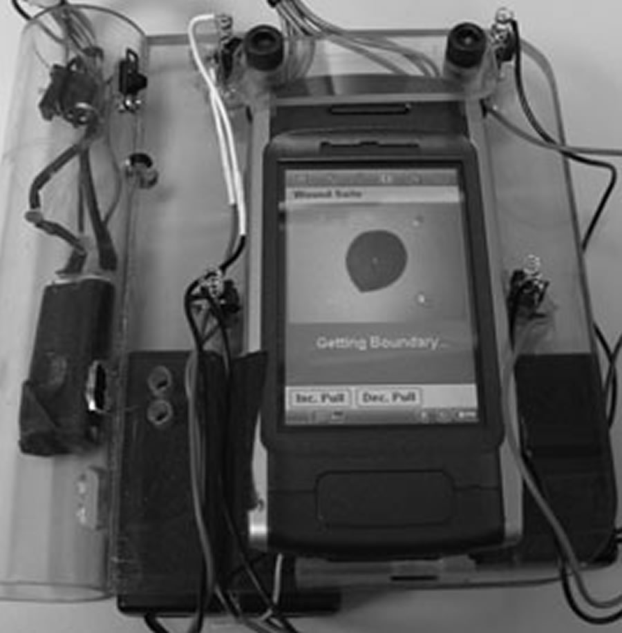 Figure 1: Device from Top Side (Click for larger view)
 The design is based on the use of structured lighting and other computer vision techniques to measure the wound; this required complex algorithmic design in conjunction with specific physical structure. The prototype device is made up of two main physical components. One is the handheld device that is similar in form to a PDA. This is the interface through which the user interacts with the system and through which data collection is done. The other component is an image processing server built on a laptop where the majority of image processing is done. The two components communicate (i.e. transfer images, data, etc.) via a Bluetooth connection. This two component system was chosen for the prototype to allow for rapid prototyping of the image processing algorithms; however, in the final version of the system all of the image processing will be done in a single handheld device.
The Sony-Ericsson P900 phone was chosen as the hand-held platform for the prototype device. A touch-screen interface, camera, and Bluetooth were all features available on this phone which were necessary to build the application. The phone is mounted in a dock to which 4 laser diodes (used for structured lighting), 8 white LEDs (used for scene illumination), and batteries to supply the lights are also mounted. The complete hand-held device is shown from top in Figure 1 and bottom in Figure 2.
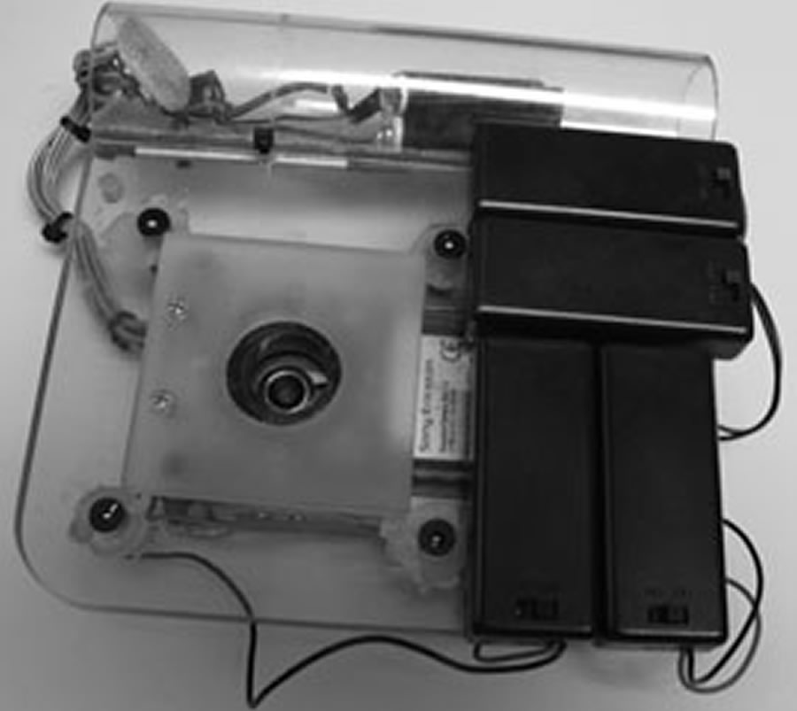 Figure 2: Device from Underside (Click for larger view)
 The lasers mounted to the dock are arranged in a square with known edge lengths and the camera lens is centered in the square. Lasers are aligned so that they are perpendicular with the z-axis of the image. This arrangement gives a known structure to the projected laser points which allows calculation of certain properties of the image. Scene illumination is done by 8 white LEDs mounted on the dock. Theses are arranged to form an octagonal shape around the camera lens. A diffusion filter is placed over the LEDs so that the lighting is spread more equally over the entire scene. We found that this lighting setup was very helpful in the clinical environment because there were many situations in which the overhead room lighting was not enough or could not be turned on. A Dell Inspiron laptop running Linux acted as the image processing server. A D-Link USB Bluetooth Adapter was used to enable Bluetooth on the laptop.
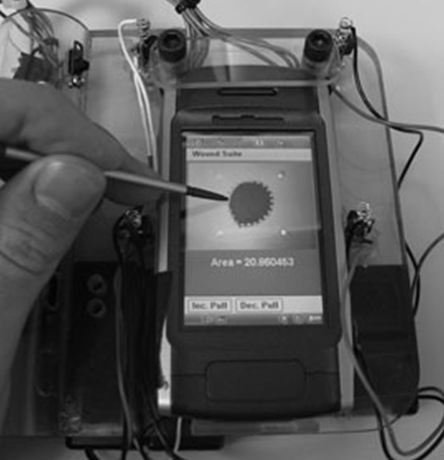 Figure 3: Correction of Proposed Border (Click for larger view)
 Software that was programmed for the phone controls the user interface and a portion of the image processing code. The major functions of the user interface are to allow the user to preview the picture, take a picture, review an automatically detected wound border, trace a new wound border, and edit an existing wound border. Figure 3 shows a user editing a suggested border. The interface also provides feedback about the wound area, state of processing, and quality of image. The other part of the phone code, image processing code, does the analysis of the quality of image taken. This analysis is done so that time is not wasted in processing a poor quality image. Checks are made to see if there are four laser points in the image and to see if the skew of the image is below a certain threshold. If either of the checks fails, the user is prompted to take another image or to attempt to process the image anyways.
Software on the server is programmed in MATLAB (The MathWorks, Inc) for rapid prototyping. It has several functions which include skew correction, area measurement, and wound border detection. The first two are based on analysis of the structured lighting; the latter is based on edges in the image. As previously mentioned, the structured lighting used for this device is created by 4 parallel lasers arranged in a square around the camera lens. In order to analyze this lighting, the lasers must first be detected. Our device implements an algorithm to automatically detect the lasers based on a model of the lasers. The algorithm has performed with 100% accuracy on all of our clinically captured images.
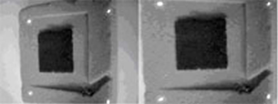 Figure 4: Skew Correction (Click for larger view)
 Skew correction involves calculation of the orientation at which the image was taken and then reshaping of the image so if it were taken from the correct orientation. Correction of an image is shown in Figure 4. This step is necessary, because if the device is held at orientation that is not parallel to the wound bed when the picture is taken, then the resulting image will be skewed. This skew can result in an incorrect area calculation if not first corrected for.
Area measurement involves determining how much physical area in the real world a single pixel in the image maps to. To calculate this, the average distance in pixels between laser points in the image is calculated. The ratio between real world distance (in cm) of the lasers and the image distance (in pixels) of the lasers is calculated to give a mapping from pixels to cm. This mapping is used to calculate the real world area of the wound as described below.
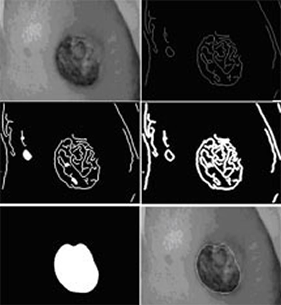 Figure 5: Border Detection (Click for larger view)
 Wound border detection is the process of identifying a probable border for the wound. We implemented an iterative edge detection algorithm for this purpose (demonstrated in Figure 5). The algorithm works under the assumption that the edges in the image provide identifiable information about the wound border. Once the border is identified it is sent to the phone and drawn on the wound image for the user to view. If the user rejects the border, the border can be edited by pushing or pulling it or the user can choose to completely redraw it. Once the user obtains a satisfactory border, the area of the wound is calculated. This area is calculated by counting the number of pixels circumscribed by the wound border and then multiplying that value by the pixel area measurement.
RESULTS
We ran the prototype device through several tests of quality of measurement and proof of concept. Space limitations prevent us from a through presentation of testing methodology, but we will briefly describe the results. Repeatability of hand drawn wound borders by multiple testers had a coefficient of variation of <7% and <10% for well defined ulcers and poorly defined ulcers respectively. Standard deviation of measurement at different distances and skew was approximately 3.5%. Standard deviation of measurement was also evaluated for 3 size groups of pre-segmented wounds. Standard deviation times 1.96 (gives the 95% confidence interval) was 2.4%, 3.5%, and 10.5% for wounds >40cm2, 10~40cm2, and <10cm2 respectively. Compared to the results given in Plassman et al (6), this device is capable of out-performing Kundin gauge, transparency tracing, photography, and is comparable to other structured lighting methods.
Clinical proof of concept testing showed that the device was capable of performing in a clinical setting; however it also revealed some weakness in the current implementation. We encountered a wider variety of wound shapes in the clinic than we had previously tested the algorithm on. It turns out that for the majority of wounds with irregular shape, the suggested border needed at least some minimal adjustments. We also got some feedback from clinicians who observed the usage of the device1. In general they expressed excitement and intrigue about the device and were interested in using it. Most also expressed a common concern that the processing time was too long. It seems that in relation to the several seconds it took for the clinician to do their current measurements, the <1min of processing is very long.
CONCLUSION
The wound measurement device we presented is a low-cost, non-contact, hand-held measurement device that is capable of providing high-quality measurements. With these characteristics, it is plausible that its cost to benefit ratio could allow it to replace those methods so widely employed today. The next step in development is to transfer the technology to a new mobile computing platform resembling the final device. This version will be a single hand-held unit on which all of the processing takes place. We have selected components which we believe are powerful enough to do the required processing and allow us to meet the cost of goods goal of $100. Although the processing power of this device will be somewhat less than that of the processing server, efficiency will be improved by removing the data transfer and rewriting code in C++. With this we will do further clinical testing and also user interface testing.
ACKNOWLEDGMENTS
We would like to thank Dr. Stephen Sprigle, Dr. Thad Starner, and Kim Davis for guidance along the way. We would also like to thank Cathy Koerner for letting us do our clinical testing. Additionally, we thank Jonathan Jowers and Daniel Smith for help with mechanical and electronics construction.
REFERENCES
- Kundin, J.I., A new way to size up wounds. American Journal of Nursing, 1989: p. 206-207.
- Jones, C.D. and P. Plassman, Mavis-II: Measurement of area and volume instrument system for skin wounds, University of Glamorgan in Wales, UK.
- Krouskop, T.A., R. Baker, and M.S. Wilson, A non contact wound measurement system. Journal of Rehabilitation Research and Development, 2002. 39(3): p. 337-346.
- Plassman, P. and T. Jones, MAVIS: a non-invasive instrument to measure area and volume of wounds. Medical Engineering and Physics, 1998. 20(5): p. 332-338.
- Whiston, R.J., J. Melhuish, and K.G. Harding, High resolution ultrasound imaging in wound healing. WOUNDS: A Compendium of Clinical Research and Practice, 1993. 5(3): p. 116-121.
- Plassman, P., J.M. Melhuish, and K.G. Harding, Problems of Assessing Wound Size, Wound Healing Research Unit, University of Wales College of Medicine, Cardiff CF4 4XN, Wales, United Kingdom.
Primary Author Contact:
Mark G. Duckworth
490 10th Street
Atlanta, GA 30318