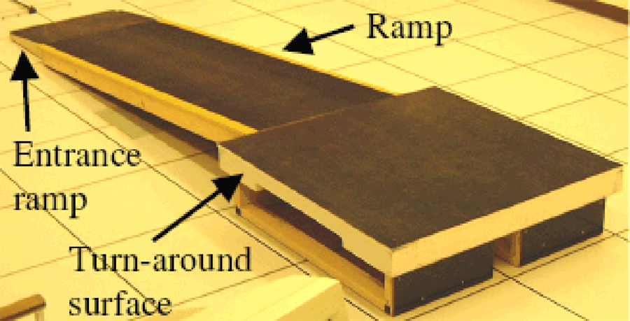
Figure 11 : Photograph of the incline ramped walking surface. The “Ramp” portion is supported by force plates, and is separated from the “Entrance ramp” and “Turn-around Surface” in order to eliminate mechanical interactions between them. The small entrance ramp helped to ensure that subjects would not stub their toes as they approached the ramp. Hand rails (not shown) were placed on both sides of the ramps in case the subject began to fall, though subjects were instructed to avoid using them during walking. Subjects were instructed to walk up the ramp, turn around on the top platform, and walk back down (data could be taken for approximately three steps in each direction). The ramp was supported on both ends by force platforms so that ground reaction forces and center of pressure (COP) of ground reaction forces could be measured, thus enabling the calculation of roll-over shapes (see Figure 12). From (8).