Cradle To Grave Design Of A Sip Actuated Leg Bag Valve
Matthew Heidt, Tim Ponshock, Chris Esser, Robert Bradford
ABSTRACT
Current leg bag valves (LBV’s) allow users to drain their leg bags mechanically by pulling a cable, or electrically by hitting a switch or with a sip-n-puff system. With a mechanically operated valve, sufficient mobility and strength is needed to actuate the valve. Electrically operated valves require a power source and external cables. In addition, current valves do not provide easily accessible parts to the user, reducing the life-span of the valve. This report will present the “cradle to grave” design of a pneumatically operated leg bag valve that:
- Requires no external power or upper limb mobility
- Operated by a sipping system
- Maintainable for infinite life
- Simple fabrication
Keywords:
Leg bag valve, sip-n-puff, and pneumatically operated
BACKGROUND
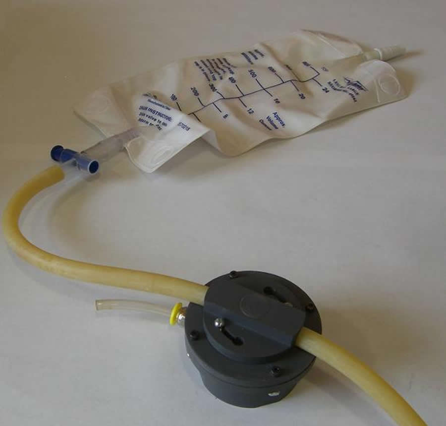
Figure 1: Valve with “Bonnet Style” Body Type Attached to Leg Bag and Drain Tube (Click for larger view)
A user of a pneumatically operated leg bag valve approached us with problems related to the valve. Through him, it became clear that use of a remotely operated leg bag valve allows the user to increase their independence by eliminating the need for assistance in draining the urinary bag. However, currently marketed valves are either electrically or mechanically operated and as a result have several inherent problems. First, the method of activation, mechanical pull cable or electric, make these valves susceptible to unintentional activation or loss-of-use. This becomes a larger issue if the user has spasticity since leg spasms could result in unintentional activation of the mechanical valve or, in the case of the electric valve, disconnection of the power wires thus rendering the electric valve unusable. In addition, current valves are expensive with prices ranging from $230.00 for a mechanical system [1] to $475.00 for a sip and puff electric system [2]. Finally, the current valves do not allow the user to disassemble the valve for cleaning or replacement of individual parts to prolong the life of the valve.
As the problems mentioned above were investigated, it became apparent that mechanical and electrically operated leg bag valves fail to meet the needs of many users, and we determined that a redesign of the pneumatically operated valve would be the best way to meet the most users’ needs from their leg bag valve. The following sections describe the process followed to create a leg bag valve system designed from cradle to grave that will overcome the flaws in currently available valves.
OBJECTIVES
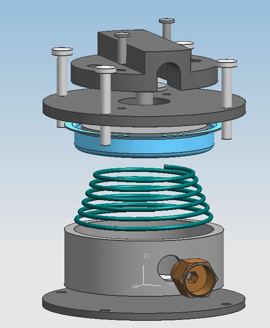 Figure 2: Exploded View of the Entire Valve (Click for larger view)
 The lack of a leg bag valve that meets certain customer requirements has created a need to develop a new solution. Our objectives for this new valve are the following:
- Provide an alternative LBV for users whose needs are not met
- System independent of electric power
- Minimal effort to operate
- Inconspicuous
- Create a product with an infinite life
- Provide multiple ways of acquiring the valve
- Make a reduced cost valve compared to current valves
METHODOLOGY
Utilizing a “classic” design approach, we first developed a Quality Function Deployment (QFD) which allowed us to determine customer requirements, and then rank each valve on the market. This ranking evaluation gave us the direction for our design work. Once the QFD was completed and a user was interviewed, we were able to come up with a final set of design objectives.
DETAILED DESIGN
The Valve
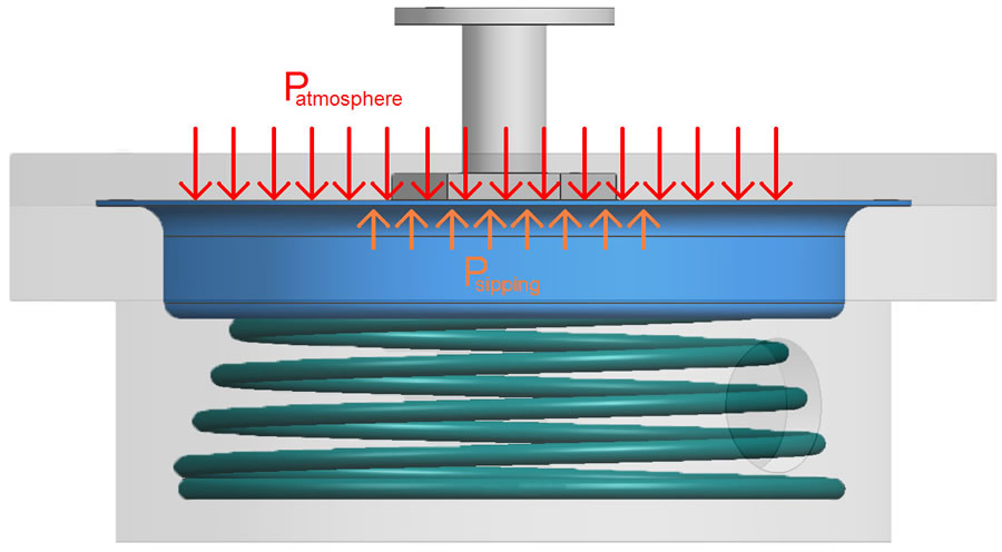 Figure 3: Interior Parts of Valve During Draining (Click for larger view)
 The design can be seen in Figure 1. It was designed to be as small as possible while still being able to function correctly. It is 3” in diameter, and 1” tall, and approximately .34 lbs in weight, which allows it to be inconspicuous under a user’s pant leg. It also incorporates rounded screw posts with no sharp edges which eliminate the possibility of injuring the user.
Operation
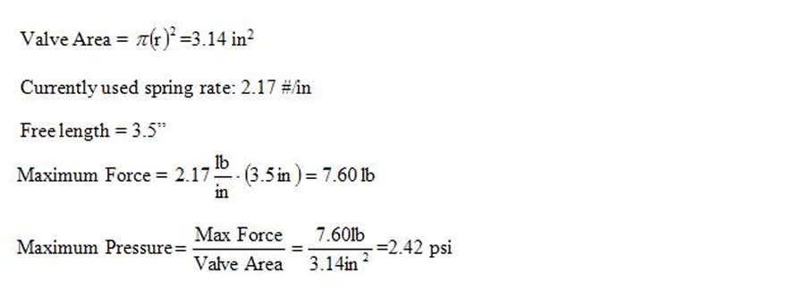 Figure 4: Equations for Theoretical Max Sipping Pressure Required (Click for larger view)
 The valve was designed to operate with minimal moving parts for ease of operation. The valve works by creating a vacuum pressure under the diaphragm with the sipping tube. Above the diaphragm, atmospheric pressure is present. Once the vacuum is created, the imbalance in forces moves the diaphragm down, retracting the plunger, which releases the force on the drain tube. The plunger’s bolt height is also adjustable, which will ensure that it is completely pinching the drain tube when closed.
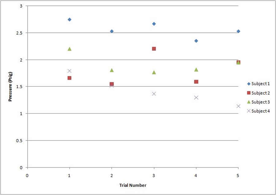 Figure 5: Plot of Four Subjects’ Sipping Pressures Deemed Comfortable (Click for larger view)
 With the current spring, the maximum operating pressure was found to be 2.42 psi. After experimentally determining sipping pressures, we found users averaged 1.92 psi. However, when the user’s used their tongue to hold the pressure and sip again, they could attain higher values comfortably, which allowed actuation of the valve.
Fabrication
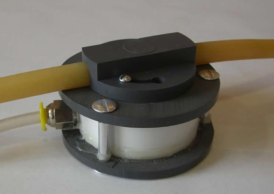 Figure 6: “Sandwich Style” Body Design of Valve (Click for larger view)
 The pneumatically actuated leg bag valve is designed for fabrication in three different ways, depending on customer requirements. Plans are provided to build the valve at home using off-the-shelf materials. For at home construction, a “Sandwich Style” body was designed (see Figure 6). The body is constructed of stock clear polycarbonate tubing that can be cut to size. Both ends of the valve have stock acrylic discs which are held together by screw posts available at a hardware store. Other stock parts include a bolt for the plunger, the quick connect inlet, and the twist on cover screws. The holes for the screw posts are drilled and the holes for the screws to secure the twist on cap are threaded.
![Figure 7 shows a basic diagram of a mechanical Exhaust Gas Recirculation Valve used in an automobile [3]. At the vacuum port, a vacuum created by the emissions causes a pressure imbalance at the diaphragm, compressing the spring. This well established technology could be “piggy-backed” for the design of the leg bag valve. The spring and diaphragm used in the leg bag valve are available from a stock EGR valve.](Bradford/Drawing3.jpg) Figure 7: Diagram of a Negative Backpressure EGR Valve (Click for larger view)
Figure 7: Diagram of a Negative Backpressure EGR Valve (Click for larger view) Plans are provided to have the twist on cover machined by a skilled professional, as it requires machinery most do not have. The spring is custom and may be purchased from a spring manufacturer for about $15. Also, the diaphragm may be purchased as a stock item. The estimated cost of fabrication for this design is $70.73 as shown in the Sandwich Parts List. As an alternative source for the spring and diaphragm, a spring and diaphragm from an Exhaust Gas Recirculation Valve could be used (see Figure 7).
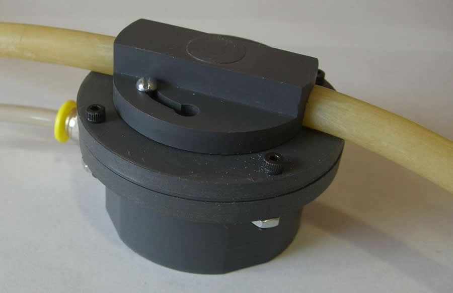 Figure 8: “Bonnet Style” Body Design of Valve (Click for larger view)
 Another design for the body was developed for customers who wish to take plans to a skilled laborer, such as a machinist, for fabrication. This design has a “Bonnet Style” body, combining the bottom disc and cylinder pieces from the Sandwich Style body into one machined piece of clear polycarbonate called a bonnet, as shown in Figure 8. The advantages of this design are improved durability and vacuum sealing with no significant weight addition. In this design, round headed bolts and nuts are used to secure the top disc to the machined bonnet piece. The remaining parts are the same. The estimated price of the Bonnet Style body is $90.26 including machining costs, as shown in the Bonnet Parts List.
Finally, drawings of the Bonnet Style body design are available if a company is interested in producing the valve. In this case, the Bonnet Style valve body would likely be injection molded at a significantly reduced fabrication cost (after tooling).
Maintenance and Replacement
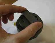 Figure 9: Twist On Cover (Click for larger view)
 Since the valve will be subject to both user and environmental moisture, we designed the valve to be maintainable and easy to clean. To accomplish this we incorporated a quick connect sipping tube which can be seen in Figure 6. This allows for cleaning of the port and replacement of the sipping tube. A twist on cover was also incorporated to allow for simple cleaning and ease in assembly/disassembly as shown in Figure 9. The body of the valve was also chosen to be clear to allow the user to determine if the valve needs cleaning.
One of the most important aspects of our design was to provide an affordable replacement. The body of the valve itself was constructed of simple, affordable, and easily attainable parts which are included in the parts list.
References
- JB-3 Leg Bag Emptier. http://www.jb-3.com.
- R.D Equpiment, Inc. http://www.rdequipment.com .
- 4th Gen F-body Exhaust Gas Recirculation (EGR) System. http://shbox.com/1/EGR_valve.jpg
Author Contact Information
Robert Bradford
W171 N4901 Greenview Avenue
Menomonee Falls, WI 53051
414-534-4771
Matthew Heidt
5601 Hilldale Rd
Slinger, WI 53086
262-689-8486