Integrated Functional Electrical Stimulation-Ankle Foot Orthosis Training System
Jennifer Hadley, Jonathan Steer, Kristi Tanouye
ABSTRACT
Cerebral Palsy (CP) is a non-progressive neurological disorder which develops in-utero or after birth. Current treatment for CP includes physical therapy and braces used to increase ambulation. Ankle-Foot Orthoses (AFOs) are lightweight plastic braces that secure the lower leg, ankle, and foot in a predetermined position, commonly used to aide dorsiflexion in CP patients. Another common treatment, Functional Electrode Stimulation (FES), is administered by physical therapists in order to build muscle tone and improve dorsiflexion. FES uses low energy electrical stimulation to excite either the common peroneal nerve or the tibialis anterior muscle, causing the patient to actively dorsiflex, increasing foot-ground clearance. Our device integrates an FES unit with a hinged AFO, to automate and improve the current physical therapy processes used to treat CP patients. This allows for the rapid and accurate placement of FES electrodes, which removes the major barrier to at-home administration of this therapy.
Keywords:
Cerebral Palsy, Physical Therapy, Electrical Stimulation, Ankle-Foot Orthosis
BACKGROUND
Cerebral Palsy is a non-progressive neurological disorder which develops in-utero or after birth, affecting approximately 0.2% of all children born in the United States(1). Cerebral Palsy patients are extremely diverse, and are assigned a Gross Motor Function Classification Score (GMFCM), ranging from I to V(1).
Current Methods
Current treatment for Cerebral Palsy includes physical therapy and a combination of braces and orthotics used to correct motor impairment and increase ambulation. AFOs are lightweight plastic braces that secure the lower leg, ankle, and foot in a predetermined position, and aide in dorsiflexion(2). AFOs can be custom built from plaster molds of a patient’s leg, or bought “off the shelf” according to shoe size and calf circumference(3). Physical therapists can also use FES devices to build muscle tone and decrease spasticity in patients with CP. FES uses low energy electrical stimulation to generate a muscle contraction by exciting either the common peroneal nerve or the tibialis anterior muscle. Unlike the use of AFOs, FES causes the patient to actively dorsiflex, thus activating and training their underused muscles.
Statement of the Problem
The use of FES devices requires accurate placement of the stimulating electrodes in a specific region of the patients’ lower leg(5). The difficulty associated with caregivers placing these electrodes has prevented these devices from gaining widespread use away from physical therapists’ offices(4). Electrical stimulation from an FES device can be triggered either by a sensor, usually placed beneath the patient’s heel, or manually triggered with a hand-held switch. Many patients with CP walk in a raised “tip-toe” style gait, thus heel sensors may not be activated during their normal walking pattern(4). Therefore, the less-specific manual triggering is more commonly used. Manual triggering is difficult to time to the patient’s gait cycle; this difficulty in triggering leads to imprecise therapy, which translates in to patients not receiving the maximal benefit from this treatment(5).
Scope
Our device integrates an FES unit with an AFO, to automate and improve the current physical therapy processes used to treat patients with CP. Our target patients have been diagnosed with a mild case of CP (GMFCS level I or II) and are not afflicted with a severe crouch-type gait. Ideally, they will have 5° to 25° of passive ankle dorsiflexion, so that when their muscle is activated, the foot has the required range of motion to dorsiflex.
DESIGN AND DEVELOPMENT
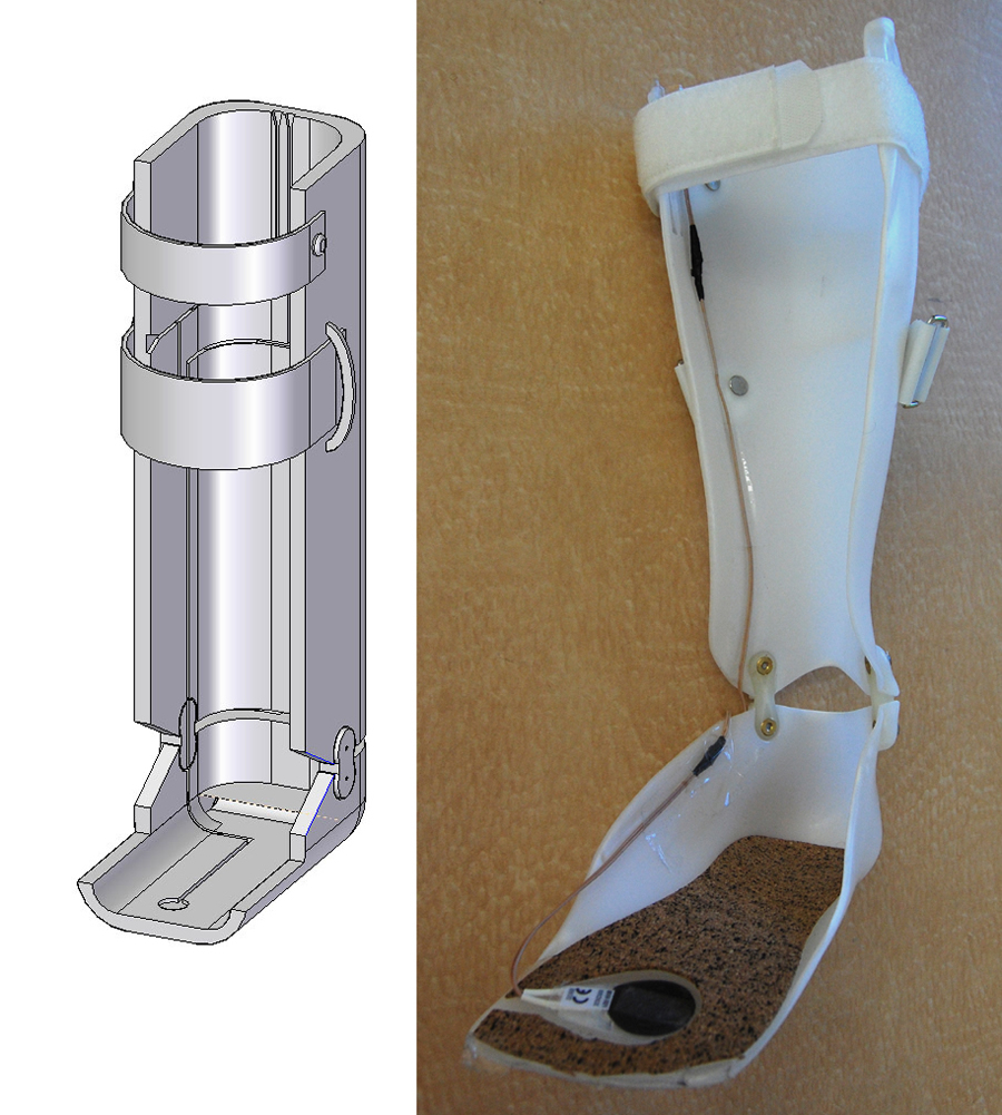 Figure 1. (Click for larger view)
 Through conversations with clinicians and orthotists, we set our to determine a set of design requirements for our device. We choose our final design through a system of weighting various categories and scoring options, choosing the option which ranked highest for all categories, reflected in the Pugh charts below.
Design Requirements
Our original qualitative requirements specified that the device be safe, comfortable, customizable, reproducible, and modular. It was also required that the device be easy to apply so that the parent or caregiver be able to easily place and control the device without the supervision of a physical therapist. Quantitative design specifications are presented in Table 1, and provide the technical specifications for this device.
| Design Specifications | Applicable Metric (AFO) | Applicable Metric (FES) |
|---|---|---|
| Small | Thickness of plastic: 3mm-5mm | 25mm x 70mm x 150mm |
| Lightweight | Does not impede patient’s gait | 200g with battery |
| Low cost | ≤ $800 per brace | ≤ $1250 per system |
| Accurate placement of electrodes | -------------- | ± 1cm around PT’s suggested placement |
| Patient sensitivity/Signal level | Does not change the fit of AFO | At least 10 discrete amplitude settings |
| Length of use | During normal activity | Up to full day, as determined by PT |
| Reliable | Last ≥ 3 years (or until outgrown) | 95% accuracy of stimulation firing |
| Durable | Withstand ≥ 2.2 kN | Withstand 2N of force if dropped |
| Battery Output | -------------- | 9V |
| Lifespan of electrodes | -------------- | ~ 2-3 weeks |
| Lifespan of sensor | -------------- | Withstand ≥ 2.2 kN |
| Number of channels | -------------- | ≥ 1 channels |
| Force can withstand (footswitch) | -------------- | ≥ force of patient during normal activity |
| Repetition (footswitch) | -------------- | Withstand normal daily activity |
| Current Amplitude per channel | -------------- | 15 to 100mA into a 1k ohm load with a asymmetrical biphasic output, 10mA to 70mA in symmetrical biphasic mode |
| Waveform type | -------------- | Asymmetrical or symmetrical biphasic voltage driven wave form |
| Pulse Frequency | -------------- | 40Hz |
| Pulse Width | -------------- | 3 to 350 microsec |
| Output time | -------------- | 0.5 to 6 sec |
| Extension time | -------------- | 0 to 1.5 sec |
| Ramping times | -------------- | 0 to 4 sec |
| AFO Strength | Will sufficiently support patient | -------------- |
| AFO Durability | Last ≥ 3 yrs or until outgrown | -------------- |
| AFO flexibility | Provides support but does not fail | -------------- |
| Heat strength of wires and coverings (during production/alterations) | -------------- | Can withstand temperatures of hot polypropylene 180⁰-200⁰C |
| Lifespan of Velcro | ≥ lifespan of AFO | ≥ lifespan of FES |
| Lifespan of snaps | ≥ lifespan of AFO | ≥ lifespan of FES |
| Lifespan of wires | -------------- | ≥ 6 months |
| Lifespan of FES device (internal components) | -------------- | ≥ 10 years |
| Battery Life | -------------- | ≥ 2 weeks |
| Operating temperature range of everything | -18⁰ through 93⁰ C | 0⁰ through 38⁰ C |
| Minimum electrode separation (based on diameter) | -------------- | ≥ 1.25” |
Design Alternatives and Prototype
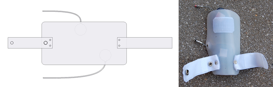 Figure 2. (Click for larger view)
In order to choose the most appropriate design, several options were considered for each of component of the device (FES, AFO, and integration). Each option was evaluated using a weighted Pugh analysis, shown in Tables 2-6, which ultimately determined the final design. The final design incorporates a custom-made, hinged AFO into which grooves for the sensor and the wires of the FES device are molded. A small, rectangular plate was added to the anterior face of the shin to attach the surface muscle electrodes. This mechanism allows for electrode positioning to be pre-set by a physical therapist prior to use of the device. The sensor was placed beneath the metatarsal line of the affected foot. Wires run along the inside of the AFO in pre-molded groves, connecting the sensor and electrodes to the commercially available FES unit, which is attached to the proximal, posterior side of the AFO using Velcro. A summary of this design is shown in the CAD drawings and photos in Figures 1-3. A primary prototype was manufactured for a group member who does not have CP, according to the specifications outlined above.
Category |
weight |
Custom-made AFO |
Pre-fabricated AFO |
| Safe (for our patient group) | 5 | 5 | 3 |
| Ease of Integration | 5 | 4 | 2 |
| Ease of Movement | 5 | 5 | 5 |
| Comfort | 4 | 4 | 2 |
| Ease of Use | 4 | 4 | 5 |
| Cost | 4 | 2 | 5 |
| Applicability | 4 | 5 | 2 |
| Reproducibility | 3 | 3 | 5 |
| Size (small) | 3 | 4 | 4 |
| Lightweight | 3 | 4 | 5 |
| Reliable | 3 | 5 | 3 |
| Durable | 3 | 5 | 4 |
| Customizable | 2 | 5 | 1 |
| Removable when not in use | 1 | 5 | 5 |
Total |
206 | 125 |
| Category | weight | Ulraflex | Hinged AFO | Unhinged AFO | Leaf Spring |
|---|---|---|---|---|---|
| Safe (for our patient group) | 5 |
3 |
5 |
5 |
1 |
| Ease of Integration | 5 |
2 |
3 |
3 |
3 |
| Ease of Movement | 5 |
1 |
5 |
1 |
5 |
| Movement Training | 5 |
1 |
5 |
1 |
4 |
| Comfort | 4 |
1 |
4 |
3 |
4 |
| Ease of Use | 4 |
3 |
4 |
4 |
4 |
| Cost | 4 |
2 |
3 |
4 |
4 |
| Reproducibility | 3 |
5 |
3 |
4 |
3 |
| Size (small) | 3 |
1 |
4 |
4 |
4 |
| Lightweight | 3 |
1 |
4 |
4 |
4 |
| Reliable | 3 |
5 |
5 |
5 |
3 |
| Durable | 3 |
5 |
4 |
5 |
1 |
| Customizable | 2 |
1 |
5 |
5 |
5 |
| Removable | 1 |
3 |
5 |
5 |
3 |
| Total | 117 |
213 |
178 |
173 |
Category |
weight |
Surface Electrodes |
Implanted Electrodes |
|---|---|---|---|
| Safety | 5 |
5 |
3 |
| Ease of Use | 5 |
4 |
5 |
| Integration | 5 |
3 |
5 |
| Reproducibility | 5 |
4 |
5 |
| Cost | 4 |
5 |
1 |
| Applicability | 4 |
5 |
1 |
| Comfort | 4 |
4 |
3 |
| Maintenance | 4 |
4 |
1 |
| Control of Movement | 3 |
5 |
3 |
| Energy Use | 3 |
3 |
4 |
| Appearance | 2 |
3 |
4 |
Total |
182 |
143 |
Category |
weight |
Muscle |
Peroneal Nerve |
|---|---|---|---|
Safety |
5 |
5 |
2 |
Ease of Use |
5 |
5 |
3 |
Integration |
5 |
5 |
3 |
Reproducibility |
5 |
4 |
3 |
Cost |
4 |
5 |
4 |
Applicability |
4 |
5 |
2 |
Comfort |
4 |
3 |
4 |
Maintenance |
4 |
5 |
5 |
Control of Movement |
3 |
5 |
3 |
Energy Use |
3 |
3 |
5 |
Appearance |
2 |
4 |
3 |
Total |
199 |
145 |
Category |
weight |
Pressure Sensors |
Tilt Sensors |
Accelerometer |
EMG |
|---|---|---|---|---|---|
Accuracy |
5 |
3 |
3 |
3 |
2 |
Safety |
5 |
5 |
5 |
5 |
3 |
Reliability |
5 |
5 |
3 |
4 |
2 |
Applicability |
5 |
5 |
3 |
5 |
4 |
Ease of Integration |
5 |
5 |
5 |
5 |
3 |
Cost |
4 |
5 |
3 |
3 |
2 |
Durability |
4 |
3 |
5 |
5 |
5 |
Movement Training |
4 |
1 |
1 |
1 |
5 |
Size |
3 |
5 |
3 |
3 |
3 |
Total |
166 |
137 |
155 |
127 |
Figures 1-3 go here
EVALUATION
Performance
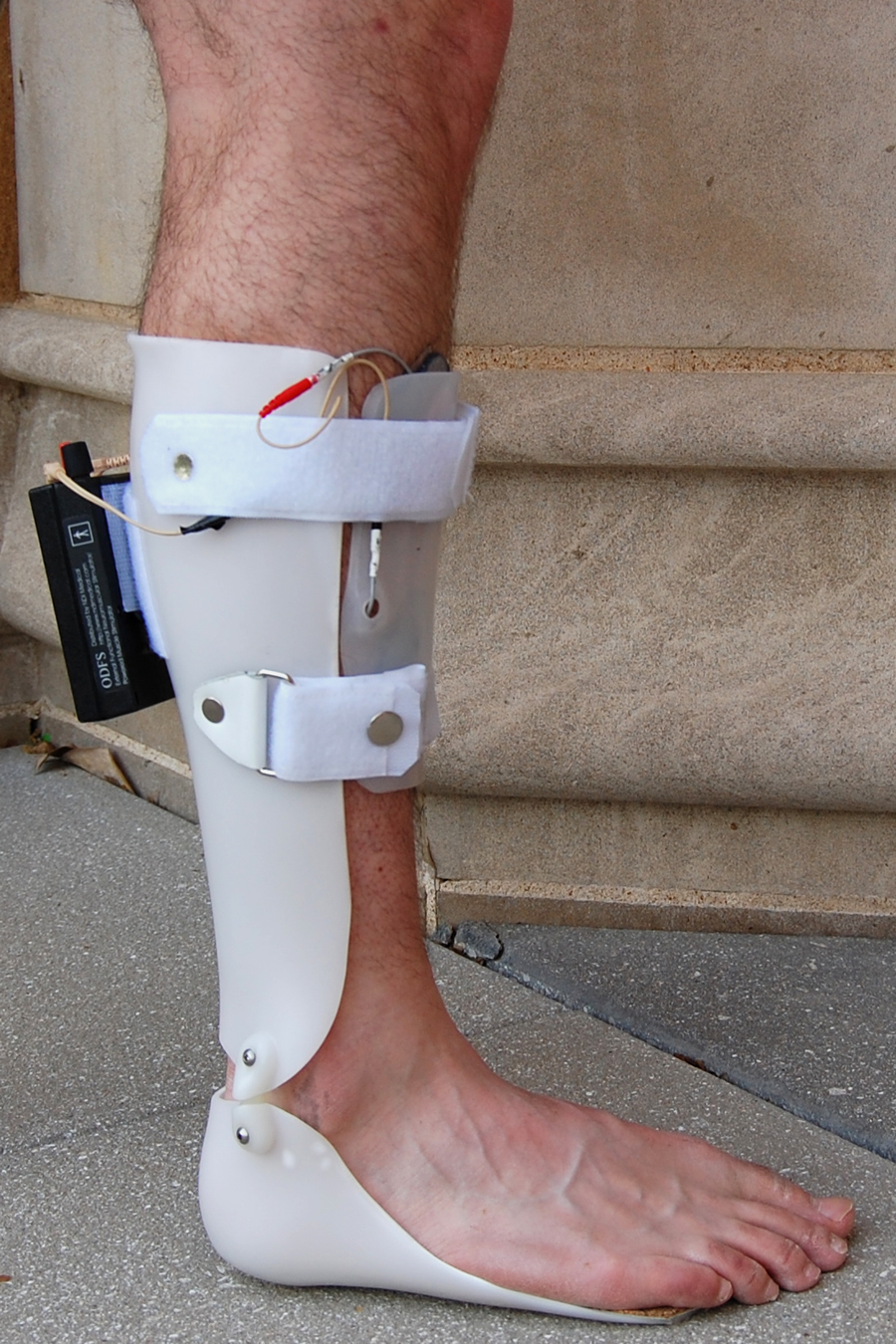 Figure 3. (Click for larger view)
 Testing of our device included verifying that the FES device worked after shortening and embedding the wires, sensor, and stimulating electrodes. We found this to be the case, and demonstrated that persons unfamiliar with our device could easily apply the device so that accurate electrical stimulation was achieved.
Safety Analysis
A thorough analysis of the safety of this device during both production and patient use was performed using DesignSafe (Design Safety Engineering); a summary of this analysis is shown in Table 7. Our analysis shows that this device is safe to produce and to use. Additionally, there are simple steps that can be implemented to further reduce risks, detailed in Table 7.
Cost
Because medical devices can be prohibitively expensive, we took great care to keep costs of our modifications reasonable. Table 8 details the actual cost of building our prototype, and estimates the cost for producing this device for patients. Additionally, while our modifications added time to the production of the AFO, this was not significant compared to the total production time, and is not reflected in Table 8.
| Component | Price | Comments |
|---|---|---|
Odstock ODFSIII + Foot Switch |
$1,250.00 |
|
Metal Snaps |
$2.92 |
|
Velcro Strips |
$2.79 |
|
Wire Connectors |
$1.90 |
|
Dummy Wire |
$1.50 |
|
Electrodes |
$0.00 |
Included with FES |
Battery |
$0.00 |
Included with FES |
AFO Production and Labor |
$0.00 |
Donated (est. cost: $315.00) |
|
$1,259.11 |
|
NEXT STEPS
We are continuing to pursue approval for human studies through our Institutional Review Board; after receiving approval, we will test our device on a small cohort of patients and evaluate its efficacy using gait analysis. After evaluating our device’s use on these patients, we plan on publishing our results in order that the entire orthopedic community could benefit from this research.
REFERENCES
- Rosenbaum et. al. “Development of the Gross Motor Function Classification System: Reliability and Validity Results.” Neurodevelopmental Clinical Research Unit. 2005
- “Ankle Foot Orthoses” Cascade Dynamic Ankle Foot Orthoses. Accessed: September 16 2007. <http://www.dafo.com>
- Smith CO LO, Keith. Interview, October 20, 2007. Orthotics & Prosthetics Labs, Inc.
- Brunstrom MD, Janice. Interview, September 15, 2007. Associate Professor, Washington University School of Medicine, Director, Pediatric Neurology Cerebral Palsy Clinic.
- Lyons. “A Review of Portable FES-Based Neural Orthoses for the Correction of Drop Foot.” IEEE Transactions on Neural Systems and Rehabilitation Engineering. Vol. 10, No. 4, Pgs 260-276. December 2002.
AKNOWLEGEMENTS
We would like to thank Janice Brunstrom, MD and Keith Smith, CO LO for their generous financial support of this project, as well as Joseph Klaesner, PhD, and Freda Branch for all of their assistance.
CONTACT INFORMATION
Jennifer Hadley, 7899 West FM 321, Tennessee Colony, TX 75861
(903) 920-1311, jahadley@gmail.com