Human Engineering Research Laboratories, Department of Veterans Affairs, VA Pittsburgh Healthcare System and University of Pittsburgh, Pittsburgh, PA 15206
ABSTRACT
The authors collaborated on the design, fabrication, and evaluation of a crutch that can be height adjusted on the fly. The benefit of this technology is that the crutch can be adjusted for use on different types of terrain such as cross slopes. The second author (an end user), another end user, and a third tester considered the on-the-fly adjustment highly useful, though design improvements and further user testing would be beneficial.
KEYWORDS
Crutches; mobility; ambulation; safety
BACKGROUND
In the United States, approximately 1.8 million non-institutionalized individuals use walkers to ambulate, 4.8 million use canes, and 566,000 use crutches [1]. Slopes, steps, and uneven terrain present obstacles to those who use walking aids.
The height adjustability of most crutches is achieved by releasing a clip, clamp, or pins so that two tubes may slide relative to each other. This is generally not done while the crutch is in use, or very often. However, the author believes from direct observation of others that a crutch that could be adjusted on the fly would give more versatility, utility, and stability than a static crutch. For example, when a person walks on a cross slope, the downhill crutch should be longer.
A number of patents in this area exist. Patent #US4252138 [2] suggests a design for quickly lengthening and shortening a crutch, for the purpose of helping an individual to rise from a chair. The design involves a spring to extend the crutch and the user’s force to contract it, using a lever release mechanism. Its mechanism resides primarily on the outside of the crutch tubes. Patent #US4237916 [3] contains a design for a crutch that is adjustable using a piston containing a mix of gas and liquid. However, the patent stops short of suggesting that this technology could be used to adjust the length of the crutch on the fly. Patent #US7350531 [4] uses a pneumatic cylinder to achieve quick adjustments of length. The intention of this design is very much like our own, but an adjustment mechanism that did not involve a gas cylinder would not infringe on this patent.
Though these patents have been filed, no on-the-fly adjustable crutch is available on the market. Some crutches such as the Navigator (Keen Mobility) contain springs to cushion the impact of weight bearing. However, the purpose of our project was not to design a shock-absorbing crutch. There appear to be no products in direct competition with our design.
DESIGN OBJECTIVE
The purpose of this design project was to develop a crutch that could be easily adjusted while in use, to allow the user to more effectively, safely, and comfortably traverse different types of terrain.
METHODS/APPROACH
Design

Figure 1: Crutch lower part, indicating release mechanism in relation to the major spring. (Click for larger view)
A potential end user and regular crutch user, who brought the design problem to the attention of the student and faculty, made major contributions to the design, fabrication, and evaluation of the prototype. A quality function deployment (QFD) diagram was constructed using important characteristics of a crutch brainstormed in class. These characteristics (such as “safe”) were translated into characteristics of a specific device (“is strong”). The end user rated the relative importance of all the characteristics. Later, during evaluation, the user rated the prototype against the same characteristics.
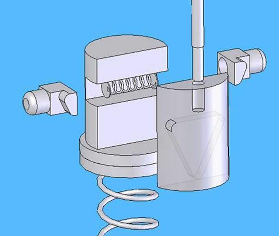
Figure 2: Final release mechanism (exploded view). (Click for larger view)
The crutch’s adjustment mechanism consisted of a release to allow two tubes to slide relative to one another, and a major spring so that the crutch would lengthen when free and shorten under pressure applied by the user (Figure 1). Two locking pins slid within a fixed track, which was inserted into the bottom end of the upper (inside) sliding tube. A small spring pushed the pins outward so that they naturally protruded from the upper tube and locked into the lower (outside) sliding tube. When acted on by the sliding ramp (which was connected to a hand lever), the pins retracted into the track and allowed the two tubes to slide relative to one another (Figure 2).
Fabrication
Friction in the system was a critical unknown in the design of the crutch. Consequently, the release mechanism was designed with two different ramp angles, a 53 degree and a 65 degree. The moving parts were prototyped using selective laser sintering (SLS). It was determined that the 65 degree ramp drew the pins in more effectively with less user effort.
The upright tubes, underarm pads, and hand grips of an existing pair of crutches were salvaged. The custom part of the prototype crutch was built using nesting tubes with a common diameter of 1". In the lower tube, a row of holes was drilled for the locking pins, and a slot was milled for a guide screw. In the upper (inside) tube, a slot was milled to accommodate the locking pins and track structure, which was then inserted inside. The crutch was assembled by attaching a rubber tip to the bottom of the lower tube, inserting the major spring (11") into the lower tube, sliding the upper tube with retracted pins into the lower tube, and securing the sections together with the set screw. This custom section was bolted to the upper section. A 24" length of all-thread was attached to the sliding ramp and used as the pull rod. Two of these prototype crutches were fabricated. Overall, the range of adjustability was ±2".
RESULTS/RESOLUTION
During the design stage, the collaborating end user provided a “user importance rank” on the QFD, which can be seen in Table 1.
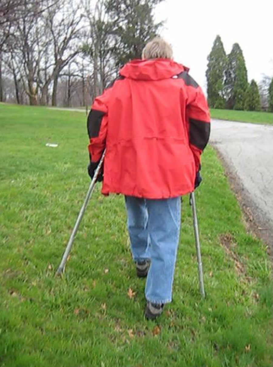
Figure 3: The on-the-fly adjustable crutches used on a cross slope. The left crutch is shorter than the right. (Click for larger view)
It was felt that in the interest of long-term durability and a less-sloppy mechanism, the SLS-prototyped parts should be remade in metal. As it was, the prototype worked well enough for testing, but there was some play in the system that made the pins lock into the holes less than perfectly at times.
The collaborating end user and another individual tested both the prototype and a regular set of crutches on a number of surfaces: on an ADA-compliant (1:20) ramp, on a steeper incline, on gentle and extreme cross slopes, on stairs, over rough terrain, and in a crowd (where the crutches cannot be splayed). The testers had sufficient physical function that these activities were all safe to perform without special precautions. An image of the crutches’ use on a cross slope can be seen in Figure 3.
A third individual, an end user, did not test the crutches but made observations. User feedback was generally positive. Comments relative to the crutch characteristics in the QFD can be seen in Table 2.
| Crutch Characteristic | User Comments |
|---|---|
| Provide walking stability | This is fine. |
| Take weight off legs | This is fine. |
| Not heavy | The prototype feels slightly heavy in swing, but usable. |
| Fits the user/ergonomic | The prototype feels very similar to a normal crutch. There should be more holes to adjust the handgrip height (not a problem unique to the prototype). |
| Easy to adjust | Very easy to adjust. |
| Quick to use | Much quicker to adjust than a normal crutch. |
| Intuitive to use | There is a low learning curve. The release mechanism feels intuitive to use. The locking pins should be able to be released manually as a failsafe. |
| Safe | Not really as it is, will be fine once the release mechanism is made of metal. |
| Affordable | The increased cost of including this feature on a normal crutch would be minimal. |
| Durable | This is fine. |
| Easy to make | Could be automated easily. |
| Weather-proof | Extreme weather could interfere with the mechanism, but probably be fine in normal weather. The mechanism could be shielded with a cover. |
| This table provides a summary of the comments given by testing users during the evaluation process. The crutch characteristics are taken from the QFD. | |
Additionally, the testers said that the height adjustability was so useful that an even greater range (>4") would be of benefit. They said that it was difficult to know visually which holes the locking pins would pop out of upon release, so some kind of auditory or visual cue would help. Overall, the testers found the crutch adjustability useful on a cross slope, going down stairs, going up a steep hill, and while walking through a crowd of people. The non-testing end user said that if the crutches were available in her size, she would definitely use them on “uneven surfaces and narrow trails” (Personal Communication, Apr. 22, 2009).
DISCUSSION/OUTCOMES/PERFORMANCE
Although the crutches were well-received, several potential design improvements are possible. Currently, adjustment is discrete with individual pin holes, though continuous adjustability might make the device easier to use. The crutches should be adjustable not only for different situations but also to fit different user heights. Users might also benefit from a two-step release mechanism that would prevent the pins from being retracted accidentally.
The adjustment mechanism could potentially be used in devices other than underarm crutches. Walker users might find it useful on stairs (where either the front two or back two feet could be shortened). On a walker or forearm crutch, the release mechanism would need to be actuated using a cable rather than a rod, to fit through curved tubes. Trail hikers could use a similar mechanism to adjust hiking poles.
COST/IMPLICATIONS
Retrofitting an existing pair of crutches with the on-the-fly adjustment mechanism was very inexpensive relative to the normal sale price of a pair of crutches (approx. $40). Approximately $70 was spent on materials; this cost would be reduced if multiple pairs of crutches were fabricated. Our mechanism could be sold as a retrofit package or built into new crutches. If production were automated for mass production, these crutches could be sold for little more than typical ones. Furthermore, because the mechanism has other applications, such as in hiking poles and camera tripods, the market may not be limited to medical devices.
REFERENCES
- Kaye, H. S., Kang, T., & LaPlante, M. P. (2000). Mobility device use in the United States Retrieved January 21, 2009, from http://dsc.ucsf.edu/publication.php?pub_id=2§ion_id=4
- Fowler, I. A. (1981). U.S. Patent No. 4,252,138. Washington, DC: U.S. Patent and Trademark Office.
- Harrison-Smith, J. L. & Milson, H. B. C. (1980). U.S. Patent No. 4,237,916. Washington, DC: U.S. Patent and Trademark Office.
- Coe, T. E. (2008). U.S. Patent No. 123,445. Washington, DC: U.S. Patent and Trademark Office.
ACKNOWLEDGMENTS
Thanks are extended to Drs. Linda van Roosmalen and David Brienza, the entire design class, and the Human Engineering Research Lab shop staff. This project was done as part of HRS/BioEng 2703 at the Department of Rehabilitation Science and Technology. Prototype development and design tools were sponsored by the Quality of Life Technology Engineering Research Center, National Science Foundation (EEC-0540865).
Author Contact Information:
Alexandra Jefferds BS, University of Pittsburgh, Human Engineering Research Laboratories, Pittsburgh, PA, 15206, Office Phone (412) 954-5302, EMAIL: anj9@pitt.edu