Amos G. Winter, V1, Mario A. Bollini, Danielle H. DeLatte, Harrison F. O’Hanley, Natasha K. Scolnik
MIT Mobility Lab, Massachusetts Institute of Technology, Cambridge, MA, USA
ABSTRACT
Mobility aids that are currently available in developing countries do not fully meet users’ needs. People require a device that is maneuverable within the home and that can travel long distances on rough roads. In this work we present the Leveraged Freedom Chair (LFC), a wheelchair-based mobility aid capable of navigating virtually any terrain, from rural walking paths to within the home, by optimally utilizing upper body power for propulsion through a variable-speed lever drivetrain. Instead of using multiple gears to change speed, the user varies mechanical advantage by sliding his hands up and down the levelers. Changing user geometry instead of machine geometry enables the lever system to be made from a simple assembly of low-cost bicycle parts. This insures the LFC can be manufactured and repaired anywhere in the developing world.
KEYWORDS:
Lever, wheelchair, drivetrain, variable speed, developing countries
INTRODUCTION
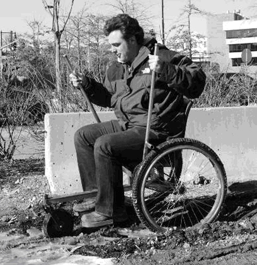
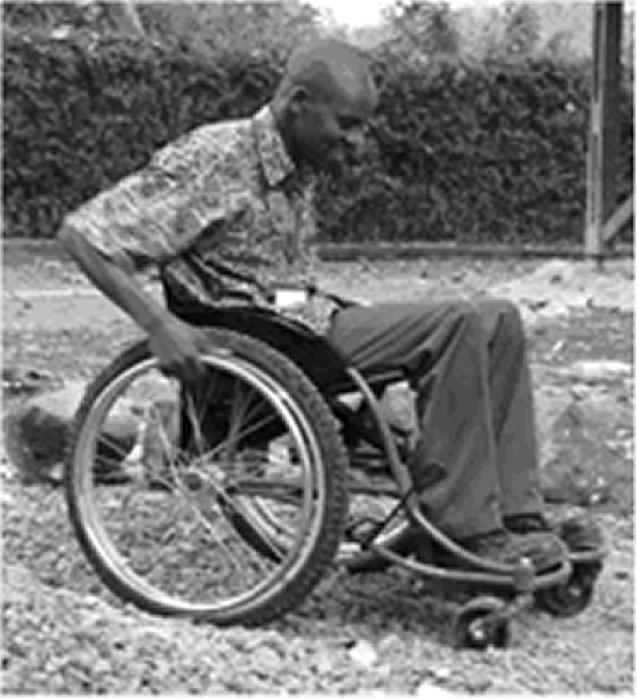
The Leveraged Freedom Chair (LFC), shown in Fig. 1a, is a wheelchair-based mobility aid that can be made anywhere in the world with off-the-shelf bicycle parts and cope with varied terrain ranging from steep hills to sandy roads to muddy walking paths. For indoor use, the LFC can operate as a regular push rim wheelchair by simply removing the levers. The motivation behind this project is to provide mobility to people with disabilities in developing countries no matter their location, travel requirements, or local environment. A mobility aid that can meet these requirements is desperately needed, as 20 million people in the developing world require a wheelchair (1) but only about five percent actually have one (2). Public transportation is rarely an option, as 70% of the developing world disabled live in rural areas (3). Even if busses are available, people with disabilities are often charged double to bring their wheelchair onboard or flat-out turned away because of discrimination (4). Products that are currently available in developing countries can not fulfill the wide usage needs of the disabled. Conventional western-styled wheelchairs, as shown in Fig. 1b, are inefficient to propel (5) and are exhausting to use for long distances on rough roads. Hand-powered tricycles (Fig. 1c), which are preferred if the user has adequate torso stability (4), are more efficient to propel than a wheelchair (5-7) and cost less due to the incorporation of standardized bicycle components. Unfortunately, tricycles are difficult to maneuver through sand and up steep hills, and are much too large to use within the home.
 |
 |
 |
| a. LFC | b. Wheelchair | c. Hand-powered tricycle |
LFC DRIVETRAIN DESIGN
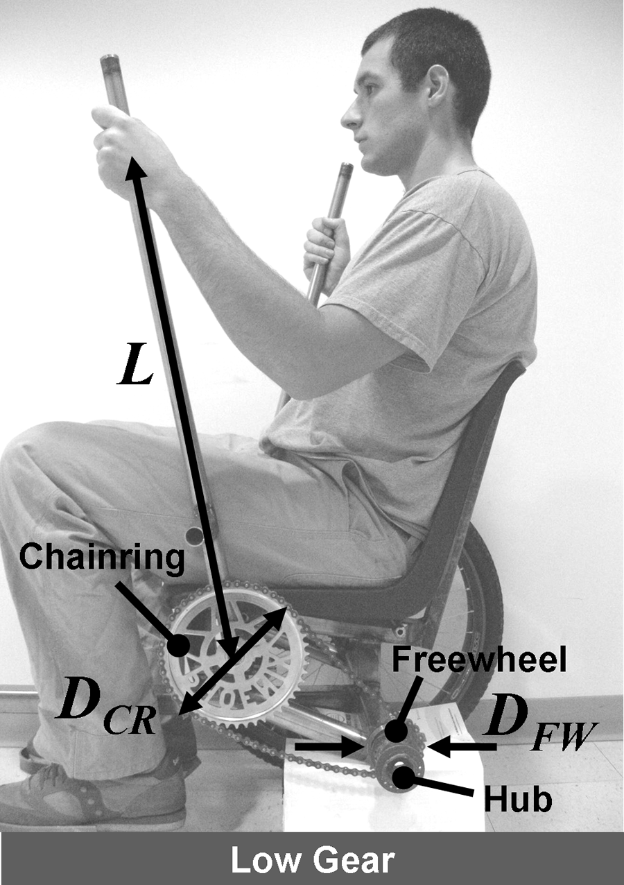
The LFC achieves a multi-speed, fixed gear ratio drivetrain with the lever system shown in Fig. 2. Unlike most gear trains, which operate in varied states to obtain multiple ratios, the LFC’s drivetrain exists in only one state; it is the user who changes his hand position to change the mechanical advantage of the device. If more torque at the wheel is needed to climb a hill, the user simply slides his hands up the levers and away from the pivots, as shown in Fig. 2a. If more speed is required, the user moves his hands closer to the lever pivots, as shown in Fig. 2b, achieving a greater angular deflection with every push stroke. The relationship between chair speed and hand speed is represented by Eqn. 1
Equation 1
V Chair /VHand = DCR RW /DFW L
where VChair is the chair velocity, VHand is the users hand velocity, DCR is the chainring diameter, RW is the wheel radius, DFW is the freewheel diameter, and L is the lever length.
 |
 |
| a. Low gear: moving hands high on the levers produces high torque | b. High gear: moving hands low on the levers high angular speed |
The design of the LFC gear train geometry was driven by human power and force capabilities. Available upper body pushing power for propulsion at maximum efficiency (30% increase in heart rate from resting) was determined by adapting results from Woude, et al (6), and was calculated to be 19.6W with a pushing force of 58N and hand velocity of 0.38m/s. Maximum attainable pushing force was determined to be 365N from US military tests on aircraft control sticks (8) – an interface geometrically similar to the LFC levers. These data were combined with the anticipated terrain in developing countries to determine the required lever size depending on resistance forces caused by rolling friction, air friction, and gravity. Road surface properties used in our analysis varied from tarmac to gravel to mud to sand, corresponding to rolling friction coefficients ranging from 0.005 to 0.5 (9, 10), and slopes between 0° and 40°, just beyond the backwards tipping angle of the LFC. Through our analysis we found that levers that can be grasped between 22cm to 86cm from the pivot will enable the rider to operate at maximum efficiency on common terrains (coefficient of rolling friction from 0.005 to 0.1 and slopes up to 5°) and generate enough torque at peak force output to overcome extremely harsh terrains (coefficient of rolling friction up to 0.45 and slopes up to 30°).
LFC PERFORMANCE TESTING AND COMPARISON TO EXISTING MOBILITY AIDS
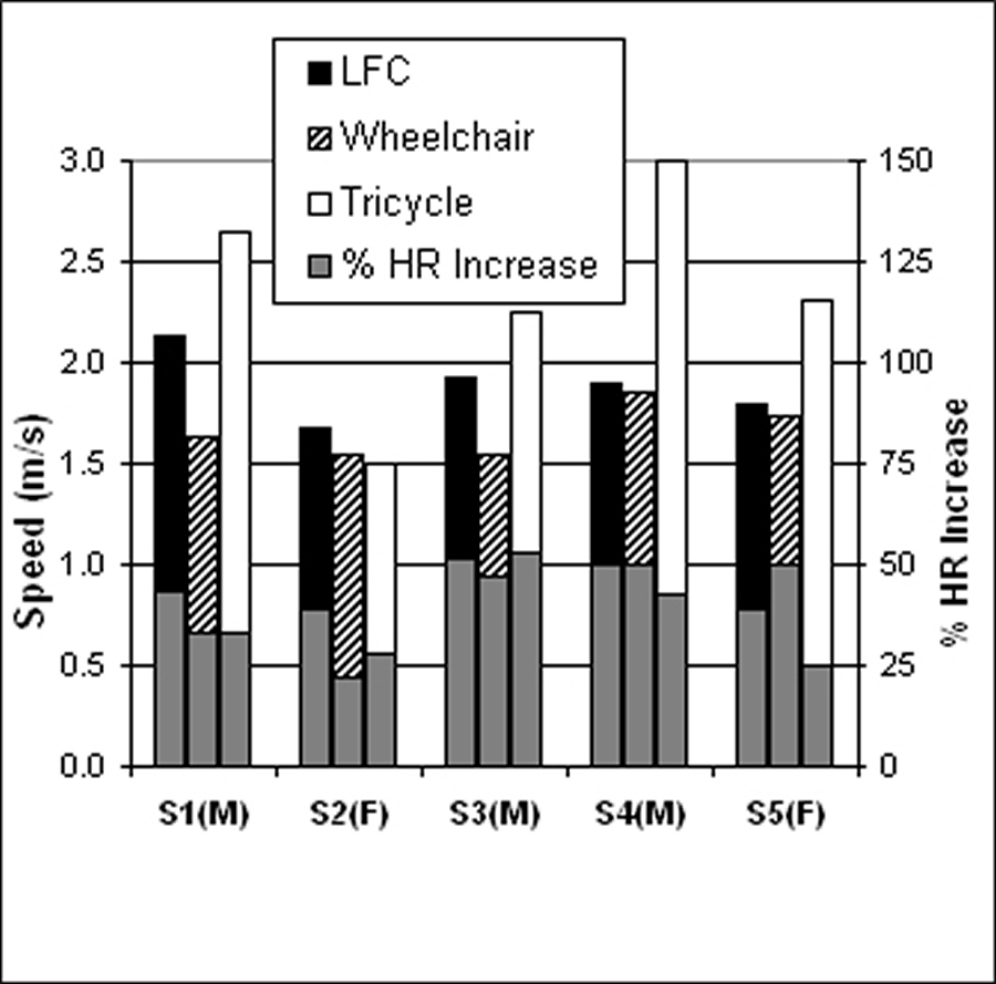
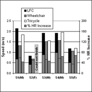
The LFC was tested in various environments and operating conditions against the East African wheelchair and tricycle pictured in Fig. 1. The first trial was an endurance test on level, smooth terrain. Five test subjects, three male and two female, ranging from age 22-29, none of whom regular wheelchair users, rode each mobility aid 0.87km (0.54miles) on a course through the MIT campus. The subjects were told to travel at a comfortable, relaxed pace that they could maintain throughout the trial. Results from the trial are shown in Fig. 3a. The mean LFC velocity for the team was 1.89m/s. The wheelchair was 11.7% slower with an average velocity of 1.67 m/s, and the tricycle was 24.3% faster at 2.34m/s. Percent increased heart rate from rest for the LFC, wheelchair, and tricycle were 44.5%, 40.5%, and 36.4%, respectively.
 |
 |
| a. Endurance test results | b. Hill climb test results |
The second test was a hill climb trial to measure high power output performance. The hill used was a stepped, concrete indoor ramp composed of 1:12 slope sections, with an overall run of 42.1m and rise of 2.9m. Results from the trial are shown in Fig. 3b. The LFC had the fastest team-averaged velocity up the ramp at 1.59m/s, with the wheelchair 22.7% slower at 1.23m/s and the tricycle 17.9% slower at 1.31m/s. The exertion levels for each mobility aid were similar, with increased heart rate from rest for the LFC, wheelchair, and tricycle 55.3%, 50.8%, and 55.9%, respectively.
The final tests were conducted outdoors on ultra-high resistance surfaces in order to simulate the limits of what could be encountered in a developing country. The LFC was able to travel through snow, with a measured coefficient of rolling resistance that averaged from 0.21 to 0.34, with peaks as high as 0.48. It was also able to climb a 17.6° slope (1:3 rise) on wet, muddy grass. To put the formidability of this slope in perspective, the maximum allowable rise of a smooth wheelchair ramp is 1:12 according to ADA regulations (11). Both the wheelchair and tricycle were not able to move through the snow. The wheelchair was able to make it up the steep slope, but with much more exertion than required with the LFC.
CONCLUSIONS AND FUTURE WORK
The LFC is a mobility aid that is capable of traversing virtually any terrain encountered in developing countries. The variable mechanical advantage attained from the lever drivetrain enables an LFC user to travel quickly and efficiently on smooth, flat roads and produce enough torque to conquer steep hills and soft ground. The single-speed, bicycle component drivetrain allows the LFC to be built and serviced anywhere in the world at prices similar to existing mobility aids. We are confident that the efficiency, compact size, and operational flexibility of the LFC will completely fulfill the mobility needs of people with disabilities in developing countries.
In August 2009 an updated LFC prototype will be taken to Africa for four-month long trials with the Association for the Physically Disabled of Kenya (APDK). This new version of the LFC will include removable levers, a lightweight frame, and a fully supportive wheelchair seat/cushion. Six prototypes will be manufactured with APDK and distributed to regions of Kenya with differing terrains. User feedback will be collected in January 2010 and used to refine the design. When the design is finalized, we plan to start LFC production with APDK and then expand to other developing country wheelchair workshops.
REFERENCES
- Annual Program Statement. USAID, 2003.
- Warner, D., Nothing About Us Without Us: Developing Innovative Technologies For, By and With Disabled Persons 1998.
- Groce, N.E., Health beliefs and behaviour towards individuals with disability cross-culturally. Introduction to Cross-Cultural Rehabilitation: An International perspective 1999.
- Amos G. Winter, V., Assessment of Wheelchair Technology in Tanzania. The International Journal of Service Learning in Engineering, 2006. 1(2): p. 60-77.
- van der Woude, L.H.V., et al., Alternative Modes of Manual Wheelchair Ambulation: An Overview. American Journal of Physical Medicine & Rehabilitation, 2001. 80(10): p. 765-777.
- Woude, L.H.V.v.d., et al., Mechanical Advantage in Wheelchair Lever Propulsion: Effect on Physical Strain and Efficiency. Journal of Rehabilitation Research and Development, 1997. 34(3): p. 286-294.
- Linden, W.L.v.d., et al., The Effect of Wheelchair Handrim Tube Diameter on Propulsion Efficiency and Force Application (Tube Diameter and Efficiency in Wheelchairs). IEEE Transactions on Rehabilitation Engineering, 1996. 4(3).
- Cott, H.P.V. and R.G. Kinkade, Human Engineering Guide to Equipment Design. 1972, Washington D.C.: U.S. Government Printing Office.
- Wilson, D.G., Bicycling Science. 3 ed. 2004, Cambridge, Massachusetts: MIT Press.
- Avallone, E.A. and I. T. Baumeister, Marks' Standard Handbook for Mechanical Engineers. 10 ed. 1996, New York: McGraw-Hill.
- ADA, Accessibility Guidelines for Buildings and Facilities (ADAAG), 4.8 Ramps. 2002, United States Access Board.