Upper-Limbs Rehabilitation Devices
Part I - Active Devices
Oren Masory, Melissa Morris, Yannick Tobie
Department of Ocean and Mechanical Engineering, Florida Atlantic University, Boca Raton, FL 33431ABSTRACT
The motivation and design aspects of an active upper-limb rehabilitation devises are discussed. The device is based on three cable robot in which the tension at and the length of each cable is controlled depends of the mode of operation. Two other versions, in which the tension of one cable is constant, is also described.
INTRODUCTION
With increasing numbers of individuals who experience Stroke, Multiple Sclerosis, Parkinson’s Disease, Accident Injuries and other causes of neuro-motor dysfunction, the number of people undertaking physical rehabilitation is also growing. Currently, physical rehabilitation places many obstacles in front of patients. In addition to the obvious struggle to regain neuro-motor function, the costs, travel and time involved can keep even a very motivated individual from achieving the full benefit of therapy. Impaired patients are generally unable to drive themselves or work, which taxes their ability to arrive for appointments in therapist offices and handle the expenses of therapy. Matters are further complicated when insurance agencies only cover therapy expenses for a limited time[1], despite the known fact that further therapy will yield more results [2]. Finally, if the patient is able to complete an adequate amount of therapy, the therapists may find themselves overloaded with patients or bored with the process.
The purpose of this paper is to describe two different devices that were designed for the purpose of upper-limb rehabilitation: 1) A fully controlled three-cable manipulator in which the length and the tension of three or two cables are controlled; and 2) A passive device that uses three linear springs in similar configuration as the cable manipulator. All are aimed to aid both the patient and therapist in maximizing the results of the physical therapy program. With these devices, patients are being able to complete at least some of the therapy at home benefiting themselves and over-worked therapists alike [3].
PRIOR WORK
The feasible use of robotics for physical rehabilitation was first seriously considered in the 1980s. MIT created the first well-published rehabilitation robot dubbed the MIT-MANUS which has been underdevelopment for nearly two decades [4]. The problem with this device, however, is that it uses a rigid SCARA manipulator to perform the assistive functions on the patient. While the control system is careful to include safety features for the user, the possibility still remains that the robotic arm could cause serious harm to the user in the event of a malfunction. In addition, the robot currently costs tens of thousands of dollars and takes up a significant amount of space. While this is certainly not an issues for therapist offices (the MANUS’s intended habitat), the cost and size are certainly issues for anyone considering such a device for home use. This device has been used to prove that robots are at least as good as a human therapist, however [5].
There are several other designs that are using rigid robotic devices to develop physical therapy robots, but several groups are also now considering cable-driven robots. Cable-driven robots have been used for some time, though mostly for cargo transportation [6]. Their use in physical therapy offers the advantages of being light-weight, low cost, and having increased energy efficiency [7]. Cables are also more flexible so that they are easier to manufacture and allow some “give” so that there is less impact on both the device and user in the case of excessive force.
The MACARM project is one such cable-driven physical therapy robot [8]. It uses eight cables, actuated by motors located in all corners of a cubic frame, to define the position and orientation of the end-effector (a joystick attached to a square base). The patient would be expected to step inside the cubic frame and hold the joystick while it was moved in the desired three-dimensional trajectory. The possibility of cable-cable interference, as well as the problems and dangers of cable-patient interference must be addressed before this becomes a practical device for patient use.
The use of three or four cables to operate over only planar trajectories is a solution to reduce the possibility of cable interference. The use of planar trajectories is not a problem as most physical therapy motions are on a plane [9]. A team headed by researchers at Ohio University investigated planar configurations [10]. They chose to focus most of their investigations and their prototype on the four-cable configuration.
DESIGN OBJECTIVES
For the devices, described in this paper, to be useful and an improvement over tools and techniques currently available, they should have several necessary characteristics:
- Inexpensive such that it could be used in the home or as a rental
- Easy to repair to minimize down-time and operation costs
- Flexible in both programming and uses
- User friendly to both the patient and therapist
- Aesthetic and minimally disturbing in a home or office environment
- To have the ability for remote monitoring to view patient progress as well as the condition of the system itself
- Safe to be operated unsupervised by a patient who is at least competent enough to remain at the device and understand simple operating instructions and commands
The safety of anyone in the vicinity is the most important aspect. This must be maintained at all times, including while the device is unused.
In addition to general design functions, the device should be capable of completing several functions normally carried out by a therapist. Thus, the device should be able to gently guide the patient through a predefined path and be able to do so repetitively until the motion is learned. The active devices must also have the ability to provide various degrees of assistance or resistance as the task and competency of the user requires. An advantage gained over the use of only a therapist is that the device could also be used to measure the progress of the patient quantitatively, instead of only qualitatively.
MANIPULATOR WITH THREE ACTIVE CABLES
The prototype described here was developed using a tri-cable design. This provides the minimum number of actuators for full haptic feedback in all directions of the plane. It was determined that using a fourth cable, as the Ohio University team had done, would cause an unnecessary increase in the weight, size, and cost of the device.
 Figure 1. General layout of the rehabilitation manipulator’s workspace
Each cable is connected to an actuator used to control the length or the tension of the cable. The end-effector at the end of all the cables has a joystick for the user to hold during operation. This configuration then gives a triangular work area that the device may fully function in. The basic outline of the device layout is shown in Figure 1.
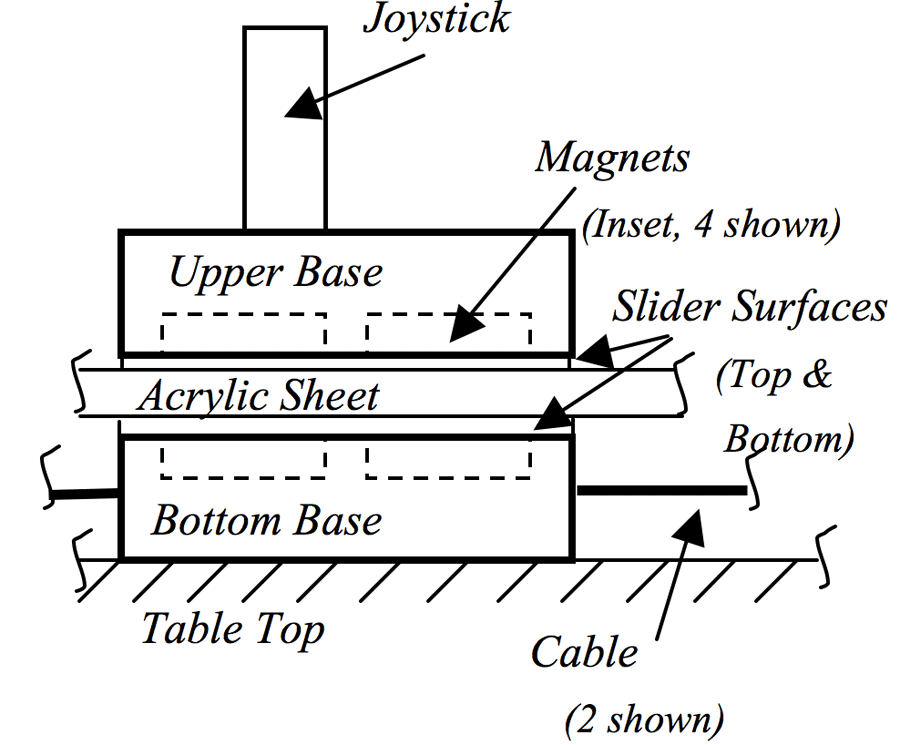 Figure 2. Side-view of the end-effector and joystick mounting
There still is an inherent problem with the possibility that the user’s arm will get entangled in the cables. This is overcome by putting a barrier between the cables and the user, as shown in Figure 2. To allow the user to still “hold” the end-effector and feel the forces applied, the joystick on top of the barrier is magnetically connected to the end-effector platform below the barrier. In this way, the user and the robot can apply forces on each other without a rigid physical connection. This arrangement provides an added safety by the “break-away” of the joystick in case of a malfunction in the manipulator’s motion. The force at which the joystick breaks away can be adjusted through the use of different magnets and distance between the two magnetic platforms.
For additional safety, a switch is located on the joystick to sense when the user is holding the joystick. If the switch is released the system will shut down. The circuitry for the device is held inside the protected area below the barrier.
The user interface was designed to be as simple to operate as possible. Since the user has limited motor capabilities, the interface incorporate only two very large buttons “Yes” or “No”. Their use allows him to navigate menus and activate features which are clearly labeled and differentiated by color and shape. The feedback and options are displayed on a LCD screen. In future prototypes, voice recognition and audio feedback are certainly possible at an increased cost.
The robot has four modes of operation:
- Play: while the patient holds the joystick the manipulator moves along a preprogrammed path in order to exercise the patient (no feedback in taken from the user)
- Assist: while the patient holds the joystick and attempts to move it along a given trajectory, printed and attached to the top surface of the acrylic sheet, the manipulator applies resistive force tangent to the trajectory at the end-effector location.
- Assessment: the robot seems passive to the user and simply being used as a measuring device that records the deviation between the required trajectory and the one the patient follows.
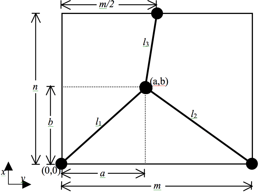 Figure 4: Kinematic layout of the work area
There can be several exercises programmed into the machine, or new ones can be transmitted via any type of connection, such as a phone line, to the therapist. The therapist can also use this communication line to retrieve information about when, what and how well the patient has performed the exercises.
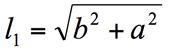
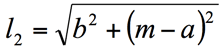
The kinematics is based upon the diagram shown in Figure 4. As shown, the x-axis will be always considered to be in the horizontal direction and the y-axis will be considered to be in the vertical direction for the duration of this thesis. Also, the kinematic origin of the work area will be considered in the lower-left corner.
Using the diagram in Figure 4 and geometric relationships, the following equations for the inverse kinematic solution were found:
 |
(1) |
|---|---|
 |
(2) |
 |
(3) |
Once the trajectory is determined the length of each cable can be determined according to Eqs. 1-3 and used as a reference to the controller. It should also be noted that the system of equations are over-constrained due to the fact that three actuators are being used for only two degrees-of-freedom system.
However, since tension is required on all cables at all times and the need to apply force in any direction, the use of at least three actuators is essential. One advantage that can be exploited is that this allows for a check that all calculations made by the processor are correct. Should there be any error, a pre-determined tension threshold (to account for rounding errors), can be used for error detection.
One problem inherent in the control of this type of system is that each cable goes slack during some point in the operation, especially during fast movements [20]. While more complex control schemes are one solution [57], this device uses a suitable control architecture as well as the very simple solution of using a slightly compliant cable to allow for some errors during motion. Though this creates some inaccuracies, the benefit of a softer feel and additional safety for the user against sudden motions is gained. The goal of this project is to create an inexpensive and functional device for generally large motions of the arms and this has been kept in mind. Allowing these small inaccuracies significantly decreases construction and controller costs and keeps the device within the stated goals of this project. Depending upon the scale and use of the system, the stiffness of the cables (or springs mounted in-line with the cables) can be adjusted to reduce or increase the free-play.
For all but the Play Mode of operation, the system must be backdriveable. This means that when the user applies force on the joystick, the system can move easily showing little or no resistance. This feature is essential for the measurement of progress in the assessment mode configuration as well the appearance of no force if the user is correctly performing a task in a therapeutic configuration. With a cable-driven design, the backdriveablity is usually obtained via force sensor measuring the tension in the cables, though a position sensor on the end-effector could be used for slow motions if there is enough flexibility in the cables to handle a slightly slower response. The slight elasticity of the cables aids in the ability of this system to be fully backdriveable by giving the motors extra time to respond.
The robot prototype in this work uses position measurements as the only means for feedback. These are taken from the encoders attached to the motors when the device is guiding the user in the Play Mode.
The assist mode requires that the device provide varying degrees of resistance to movement as the user moves throughout the work area. The forces could be exerted such that the user following the path exactly feels no resistance, but that some resistance is felt if the desired path is deviated from. The resistance felt could then be increased the further the user deviates from the ideal path. If desired, the resistance could also increase along the desired path itself in order to gently provide some speed control on the user as the path is followed. Also, a resistive force that the user has to overcome as part of the rehabilitation can be applies in various directions along the path.
In this scenario, the user initiates the movement and causes the cable tensions to change. This is picked up by the force sensors, which are being read by the microcontrollers. The microcontrollers then calculate the appropriate trajectory for each motor based upon the force to be felt by the user. This trajectory is communicated to the motor controllers to control their amplifiers and motors. The encoder data is monitored by the motor controllers which can make adjustments or send the current position back to the microcontrollers should the information prove useful in calculating the next trajectory. Overall, the bulk of the control system functions much like in the Play Mode and can use the same motor controller configuration. The main difference is that a force sensor is used to determine the user’s movements and this is interpreted by the microcontroller so that position and speed commands can be altered to adjust the perceived force.
At any position the forces have to be in equilibrium which requires:
Τ![]() 1 + Τ
1 + Τ![]() 2 + Τ
2 + Τ![]() 3 + F
3 + F![]() = 0
= 0![]() (4)
(4)
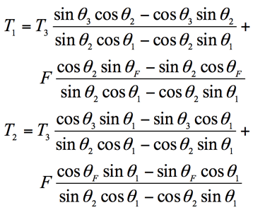
where T1, T2 and T3 are the tension in the cables and F is the force applied by the user. Expending Eq. 1 yields:
Τ![]() 1 cos
1 cos ![]() θ
θ![]() 1 + Τ
1 + Τ![]() 2 cos
2 cos ![]() θ
θ![]() 2 + Τ
2 + Τ![]() 3 cos
3 cos ![]() θ
θ![]() 3 + F
3 + F![]() cos
cos ![]() θF = 0
θF = 0
Τ![]() 1 sin
1 sin ![]() θ
θ![]() 1 + Τ
1 + Τ![]() 2 sin
2 sin ![]() θ
θ![]() 2 + Τ
2 + Τ![]() 3 sin
3 sin ![]() θ
θ![]() 3 + F
3 + F![]() sin
sin ![]() θF = 0
θF = 0 ![]() (5)
(5)
where:
As the patient applies force on the joystick, the tension must increase for two cables as the user works against them. As a result, some slackness results in the cable not in tension, as shown in the example of Figure 5. A minimum tension must be actively maintained in third cable via motor control. This minimum tension must be as small as possible while still being measurable by the force sensors that are employed.
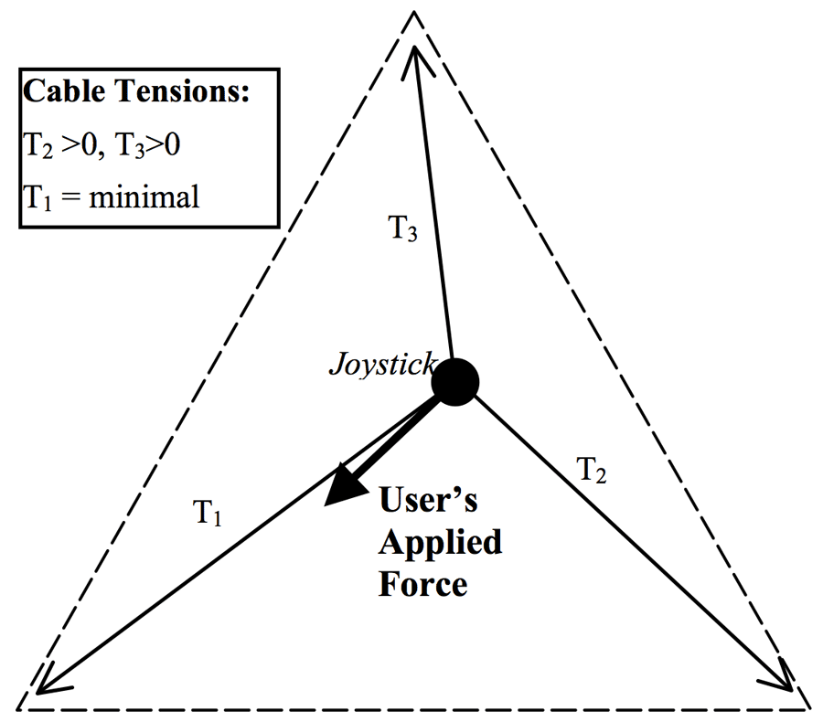 Figure 5: Example of cable tension due to user force
To be comprehensive, it should be noted that it is possible for one cable to have an increase in tension while the other two become more slack. This occurs when the applied force is directly in line with one of the cables, as in the example shown in Figure 6. It will be assumed from this point on that this case is possible and included in the discussion, though only the case with two taunt cables and one slack will be specifically mentioned.
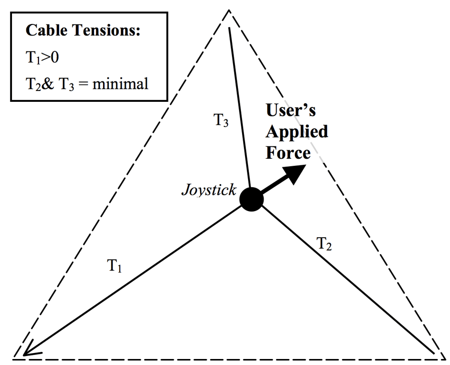 Figure 6: Example of cable tension due to user force in the same direction as a cable
To implement an increase in felt force while the user moves in a given direction, the speed of the end-effector should be slowed, stopped or reversed depending upon the desired magnitude of the force to be felt. In the opposite condition, the motors should be run at a faster speed and in the direction of the user’s movements in order to decrease the perceived force. Either way, it is a matter of correlating the direction and force of movements of the robot to that of the user in the appropriate manner.
The previous two illustrations show how the user applying a force causes the cable tensions to react. The robot, however, must use the tension measurements of the cables to determine the force of the user. This information is necessary to determine what the appropriate reaction force should be.
 Figure 7: Example of an applied force on the manipulator
Assuming one force sensor on each cable, the direction and magnitude of the user’s force is found by considering the tension on all three cables. Since the tension in one cable is minimal the magnitude and direction of the applied force can then be computed considering the tension in the other two cables and their direction (given position of the end-effector) depicted in Figure 7.
The force and direction can then be used by the motor controllers to determine the new force that should be felt given the current position of the user. This information is then used to set new tensions in all cables.
RESULTS
Current prototype implements only the play mode and force sensors have yet to be incorporated. Because the device is intended for fairly large motions of the arm, the produced errors of few centimeter are not likely to hinder the patient. Some results are shown in Figure 8. The difference between the programmed and the actual paths are due to several factors including errors introduced by the motors’ controllers, stretching of cables, and the lack of force sensors to notice changes in cable tension during movement. In addition, the equations and algorithms used to calculate cable lengths were approximated in some cases due to the resolution of the low-cost equipment used.
Future introduction of the force sensors allows for full development of the device in all four intended modes of operation.
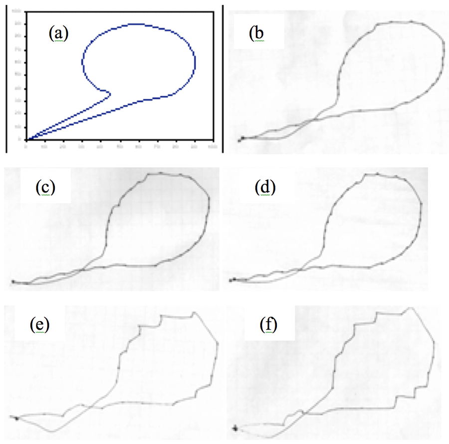 Figure 8: Actual robot circle pattern output for various maximum velocities Excel graph of pattern; Traced output at: (b) 10% of the maximum velocity (c) 25% of the maximum velocity (d) 50% of the maximum velocity (e) 75% of the maximum velocity (f) 100% maximum velocity.
Figure 8: Actual robot circle pattern output for various maximum velocities Excel graph of pattern; Traced output at: (b) 10% of the maximum velocity (c) 25% of the maximum velocity (d) 50% of the maximum velocity (e) 75% of the maximum velocity (f) 100% maximum velocity.
The results in Figure 8 show that the velocity of the system impacts the accuracy of the output if it is increased above a certain threshold. For speeds below 50% of the maximum allowable system velocity, the path is followed with about the same degree of accuracy. The speed preference could therefore be adjusted by the user or therapist to suit the goals of the therapy session. More than 50% of the maximum velocity yields the path to be somewhat jerky with more pronounced direction changes and errors do to overshooting the target position.
MANIPULATOR WITH TWO ACTIVE CABLES
Experiments with the three cable manipulator revealed that in order to maintain the required tension in the cables as well as to control the position of the end-effector, a very tight control is required. One solution to this problem is to integrate with each cable a flexible element which absorbs the inaccuracies in the cables’ length. Thus the resulted tension is accurate too
In this section two solutions, in which one cable maintains a constant known tension, are proposed.
SOLUTION I
As shown the end-effector is supported by three cables with tensions T1, T2 and T3. However, in this case only the tensions T1 and T2 are being controlled while the tension T3 is kept constant (by means of weight). Also, T3 is supported by a fixed pulley located at the middle of the top of the frame.
Since the tension T3 is a know constant, the tensions T1 and T2 can be easily determined:
 (6)
(6)
The solution above is valid as long as the values of T1 and T2 are positive (maintaining tension in the cables).
The determination of the workspace, where the above solution is valid, was determined numerically for a constant ratio of T3/F. The manipulator’s workspace in this case is shown in Figure 6 for T3/F=2:
- The red squares represent locations with unfeasible solution
- The green circles represent locations with feasible solution for any direction of the force F.
- All other points represent locations with feasible solution only for the indicated directions of the force F.
Similar to the device described in the previous section, Figure 9 indicates that the workspace of the robot is basically limited to the triangle defined by the location of the cables “anchors”.
SOLIUTION II
To enlarge the workspace of the robot, it is proposed to control the anchoring position of T3 so that it follows the X position of the end-effector.
The equilibrium equation in this case are given by:
| Τ |
(7) |
| Τ |
where
The solution for tensions T1 and T2 can be determined:
 (8)
(8)
 Figure 9: Manipulator’s workspace (T3/F=2).
The same numerical procedure mentioned above used to determine the workspace and dexterity of the robot in this case. A solution for T3/F=2 is shown in Figure 10. As shown, a major improvement in the workspace was achieved, obviously for the cost of the additional actuator needed to move the anchor point of T3. Similarly, the results in Figure 10 indicate:
- The red points (squares) represent locations with unfeasible solution
- The green points (circles) represent locations with feasible solution for any direction of the force F.
- All other points represent locations with feasible solution only for the indicated direction of the force F.
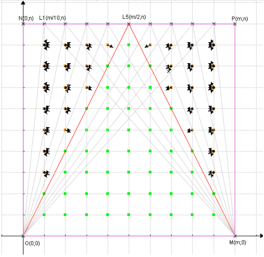 Figure 10: Results for Solution II (T3/F=2).
The solutions shown in Figures 9 and 10 are valid only for a particular tension, T3, and a load F. Changes in the ratio T3/F will affect the workspace of the robot.
Figure 11 shows the workspace and the dexterity of the robot for T3/F=5. As shown a major improvement in the workspace as well as in the dexterity of the robot was acieved. The cost for this improvement is the higher tension in the other two cables and the associated increase in cost on their actuators.
CONCLUSIONS
A robot with three controlled cables was presented. This configuration has two major drawbacks:
- It requires a tight control of the cables length and/or tension which might be difficult due to the flexibility of the cables.
- In certain positions of the workspace one or even two cable are not in tension which might cause mechanical problems.
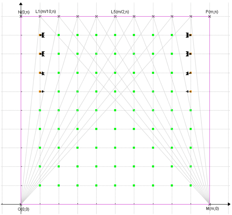 Figure 11: Manipulator’s workspace (T3/F=5).
To solve these problems two simple solutions were proposed. In the first, one cable maintained a constant tension and was anchored to a fix point. In the second the anchoring point was moved along the edge of the workspace according to the position of the joystick. Both solutions simplified the control issues and reduced the problem of “free cable”
There are many other configurations that can be explored, but we have come to the conclusion that a similar passive device can provide a solution to this rehabilitation problem.
REFERENCES
- Bullies, K. “Robot rehab.” Technology Review, 108(9), September 2005, 29-30.
- Reinkensmeyer, D.J., Emken, J.L. and Cramer, S.C. “Robotics, motor learning, and neurologic recovery,” Annual Review of Biomedical Engineering, 6, 2004, 497-525.
- Erlandson, R.F. (1995) “Applications of robotic/mechatronic systems in special education, rehabilitation therapy, and vocational training: A paradigm shift,” IEEE Transactions on Rehabilitation Engineering, 3(1), 1995, 22-34.
- Krebs, H.I., Hogan, N., Aisen, M.L. and Volpe, B.T. “Robot-aided neurorehabilitation,” IEEE Transactions on Rehabilitation Engineering, 6(1), 1998, 75-87.
- Hogan, N. and Krebs, H.I. “Interactive robots for neuro-rehabiliation,” Restorative Neurology and Neuroscience, 22, 2004, 349-358.
- So-Ryeok, O., Mankala, K., Agrawal, S.K. and Albus, J.S. “A Dual-Stage Planar Cable Robot: Dynamic Modeling and Design of a Robust Controller with Positive Inputs” Transactions of the ASME Journal of Mechanical Design, 127, 2005, 612-620.
- Hiller, M., Fang, S., Mielczarek, S., Verhoeven, R. and Franitza D. “Design, analysis and realization of tendon-based parallel manipulators,” Mechanism and Machine Theory, 40, 2004, 429-445.
- Mayhew, D., Bachrach, B., Rymer W.Z. and Beer, R.F. “Development of the MACARM – a novel cable robot for upper limb neurorehabilitation,” Proceedings of the 2005 IEEE 9th International Conference on Rehabilitation Robotics, Chicago, IL, 2005, ThB01-01.
- Johnson, M., Feng, X., Johnson, L. and Winters, J. “Potential of a suite of robot/computer-assisted motivating systems for personalized, home-based, stroke rehabilitation,” Journal of NeuroEngineering and Rehabilitation, 4(6), 2007.
- Williams, R.L., II and Gallina, P. “Translational planar cable-direct-driven robots,” Journal of Intelligent and Robotic Systems, 37, 2003, 69-96.
- Morris, M. “A Planar Cable-Driven Robotic Device for Physical Thearapy Assistance” Masters Thesis, Florida Atlantic University, Boca Raton, FL, 2007.
Acknowledgement
The authors wish to express their thanks for Florida Atlantic University support.