Dianne Goodwin, Nicholas Lee
BlueSky Designs, Inc.introduction
Over 600,000 people in the U.S. use power wheelchairs, including many with significant upper extremity limitations.(1) Chin joysticks, head arrays and sip and puff systems are used to drive their wheelchairs; and head trackers, eye gaze and switches to access speech devices or laptops. Positioning of devices is critical, but often interferes with the ability to see where they are driving. In addition to wheelchair users, many people are restricted to beds. In both situations, people need access to numerous things, such as laptops, speech devices, phones, drinks, food, medications, call systems and other controls.
Technology is under development which will enable people with little to no upper extremity use to independently move things where and when they need them. The goal is to produce an affordable range of accessible products which are easy to use and support 15 pounds.
existing technology
Currently available wheelchair-mounted robotic arms are complex and focus on using manipulators to reach, grasp and perform hand-like tasks. They are costly ($20-50,000); require considerable space; have complex controls with many degrees of freedom; and have a weight capacity too low (2-5 pounds) to support wheelchair-mounted devices such as speech devices and laptops. (5,7,8,9)
proposed product description
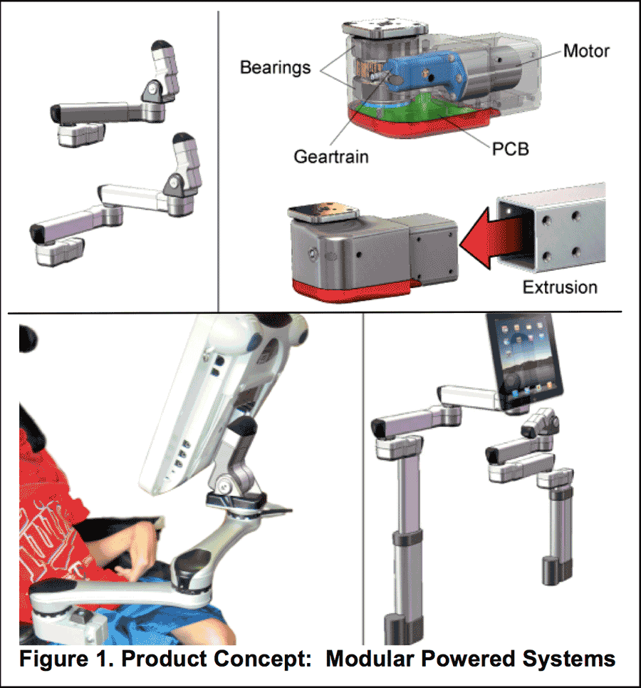 Figure 1. Product Concept: Modular Powered Systems
 The powered mounting and positioning technology under development is aimed at providing a cost-effective solution for greater independence in moving things attached to one’s chair, bed or workstation. Rather than design for manipulation of objects, the goal is simpler: to support devices and allow a person to easily move them for access and function. The system allows for custom programming of memory positions, as well as adjustment of individual joints. A person could change the tilt angle of their eye gaze device to see where they’re driving; or an over-bed support could serve as a motorized lazy susan. This way drinks, pills, a phone and remotes can be brought within reach independently, when no personal care attendants are available.
The design is modular. A Smart Joint with a microprocessor, printed circuit board, and position-sensing capabilities serves as the brain and drives the system via the motor and gears. Smart Joints can be used with manual mounts, resulting in a power tilt or rotating shoulder joint. Arms are created by linking Smart Joints to extrusions. The modularity offers a range of options from simple to complex, making it flexible, simpler and more affordable.
methods: development and testing
Product development is an iterative process which involves a concurrent focus on three areas: technical design and feasibility, accessibility and usability, and design for manufacturing. The process is iterative and cyclical, starting with a query of end users as to how things should operate before any technical development is undertaken; consideration of manufacturing process alternatives, ease of assembly, materials and cost implications as parts are designed; and a return to end users for their feedback once prototypes are developed. (4) Many aspects of the three areas overlap, with one area influencing another.
End Users & Team |
Product Design |
Manufacturing |
|
Needs: end users and teams |
x |
x |
|
End user preferences |
x |
x |
|
Ease of use/Accessibility |
x |
x |
|
Product Cost |
x |
x |
x |
Compatibility with other equipment |
x |
x |
x |
Look and feel |
x |
x |
x |
Preferences |
x |
x |
|
Manufacturability |
|
x |
x |
Ease of assembly |
|
x |
x |
Manufacturing costs (parts, tooling) |
|
x |
x |
Material options |
|
x |
x |
Safety |
x |
x |
x |
Technical development
As technology is developed, the design team goes back and forth between the End User needs and Manufacturing considerations. Design considerations include the user’s needs, preferences, ease of use; load characteristics in use; safety; manufacturing feasibility and ease of assembly; and cost implications of choices. The controls and interface must be compatible with assistive devices such as wheelchairs, joysticks, switches and speech devices.(2,3)
Mechanical design development methods include anything from sketches, to hand-made prototypes, to the design of parts and assemblies using 3D CAD software. Prototypes are used to prove technical feasibility and to get feedback from key people, such as end users, therapists and rehab engineers. Prototypes are built using in-house 3D printing or parts built by prototype houses. Depending on the stage of development and the prototype’s durability requirements, different processes and materials are used.
Before electronics are developed and programming is undertaken, the team tries to understand how people want the system to work. Various methods are used to establish “How it should work”, including “Wizard of Oz” methods or paper prototypes where you describe or simulate how it might work and seek feedback. Later in the development working prototypes are used and people interact with them. Usability testing uncovers how easy (or confusing) it is to operate.(6)
Electronics development includes: the user interface and display; accessibility and control; wireless access; movement algorithms; obstruction reactions; safety considerations; position-sensing; load-related characterization of joints; power management; and communication between the controls and joints.
Development includes design of mechanical and electronic elements and their integration. Activities are undertaken to understand the impact of the mechanical system and load on the electronics and vice versa. Different scenarios must be anticipated, tested and designed for. A device such as this will have various devices attached and will see different loads, even with the same device attached, in different situations. From a Usability perspective, the electronics must be “smart” enough allow for this with no intervention or special programming on the part of the person attaching a device or the person operating it.
For a tilting device, for example, the electronics must allow a system to overcome the initial inertia and move the load. Yet, from a safety perspective it must sense when it stops for some reason, backing off in the event it runs into a person or an object. Otherwise, it could cause damage or result in injuries.
Usability
Prototypes have been demonstrated for four key groups of “users” including individuals with disabilities, family members and professionals in the field of rehabilitation and assistive technology. Future sessions will be held in rehab settings with AT professionals, individuals with a wide range of disabilities and potential resellers. Once the device is further along and durable parts are available, it will be tested in extended trials, where a person uses it for 2-4 weeks.
Testing methods thus far have included an informal demonstration at RESNA’s developer’s forum; 3 focus groups with consumers and AT professionals at a day program for people with MS, and one with therapists at an inpatient rehab unit. Sessions included demonstration of prototypes, verbal feedback, and completion of questionnaires. General questions included: feedback as to the perceived utility; whether they would use it or recommend it; what they would use it for; anticipated payment sources; and what they thought it would cost.(2,3,4)
Very specific feedback was sought regarding key features needing to be resolved before the design could move forward. One such example, the Joint Release feature is described in detail in this paper. The Joint Release feature allows a person to move the joint, without power, for purposes of programming set points or to quickly move it in case of emergency. The design went through several iterations before it was finalized. In this case, the Joint Release feature needed to be finalized before its mating part, the Joint Housing could be released to production.
Design for manufacturing
In the Phase I project, a flexible, more modular approach to the design of a powered mounting system was developed—with a “SMART Joint” as the main building block. A SMART Joint consists of a joint housing which contains a worm gear, worm carriage, bearings, a gear, motor and Printed Circuit Board, capped off with a plastic cover which allows wireless signal 2-way transmission.
This concept not only helps in manufacturing, it allows a significant expansion of the range of options available to end users. A SMART Joint can be used singly, to offer powered tilt or rotation on an otherwise manual mount. A multi-jointed system is created by combining SMART joints with extrusions to build arms. The system is programmable, and moves quickly to user-specific positions. The Joint-Extrusion combinations allow for a wide range of projects from a few components.
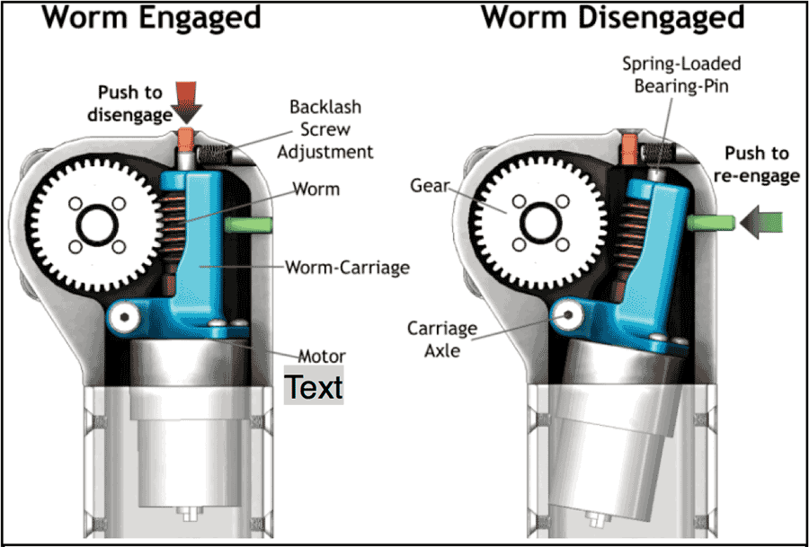 Figure 3. Initial Joint Release concept
Production considerations include design goals beyond addressing the user’s needs, such as ease of assembly, minimizing part counts, maximizing water resistance, managing tolerance issues, and keeping tooling costs low, all while assuming low production volumes.
Investment casting was chosen as the production method for the housing and worm carriage. Not only does it have low tooling costs, but the ability to cast a fairly hollow part with fewer seams makes it less permeable to water. The Unibody housing construction replaced an earlier clamshell design, reducing the part count and eliminating the need for a third tool. The redesigned worm carriage replaced a 6 part assembly. The design change resulted in fewer parts, time saved in assembly, and tighter tolerances.
The Cap on the Housing will be injection-molded plastic to allow wireless signals to and from the PCB. The plastic will be translucent, to allow the glow of LEDs on the PCB to provide visual feedback of joint status, serving as a guide to electronics troubleshooting. The extrusion is custom to achieve the tolerances we require between the housing and the joints. It serves as the connection between joints and as the housing for the battery. As one part is designed, related components are considered.
Iterative design: joint release
The design evolution of one element of the design, the Joint Release feature, is detailed to illustrate the iterative and cyclical process of product design, the importance of gathering input and feedback related to usability from end users (people with disabilities and team members), the necessity of considering mating parts, and the impact on design for production (processes, materials and cost).
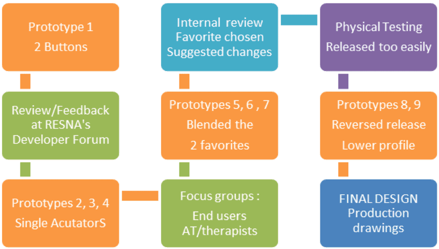 Figure 4. Iterative design process: Joint Release
 The joint is designed to hold its position without the need for power, minimizing battery draw and allowing it to hold its position when not powered. The gear train incorporates a worm gear, which drives it when the motor is operating, but holds it in position when the motor is not running.
Need for a Joint Release: Those surveyed all (100%) ranked the ability to release the joint and move it out of the way without power as Essential. The initial focus was as a safety feature, an “Emergency Release” so the mount could be moved quickly out of the way for access to an individual; but people also wanted to move it if the system was malfunctioning or had run out of power.
Additional benefits of a Joint Release relate to the ease of programming set points, and the possibility of training the arm to move through a specific path.
Design specifications of Joint Release:
- Easy to operate
- Tool-less
- Obvious/Intuitive
- Intentional/not accidental
- Cannot stick out from housing body
- Indicator/feedback when disengaged
- Incorporates the ability to adjust the gear mesh and accommodate wear
- Easy to manufacture
Joint Release evolution
Feedback on a prototype release feature at RESNA’s developer’s forum led to its redesign. The initial concept involved a 2 button user interface, where one button released the joint, and one re-engaged it (Figure 3). RESNA reviewers strongly suggested it should be a single actuator.
Three new prototypes were presented to subsequent focus groups.
As seen in Figure 4, five more were built after these focus groups. Internal testing of these showed the Release came free too easily under load, and a final redesign of the Joint Release and Housing resulted in a secure, easy-to-operate Joint Release feature. After testing with end users, internal testing, and prototype testing under loads, the team had confidence in the Joint Release design, and the joint housing was moved forward to production.
conclusion
conclusion
Product design and development is, by necessity, an iterative process in which the end user and manufacturing must be considered as the design evolves. Key features must be evaluated and designed for usability and manufacturability for a successful product to result.
This process results in a better product. In the case described, the move to a modular joint design results in more flexible manufacturing and more options for the end user. The iterative development process of the Joint Release resulted in validation of the feature’s importance and ease of use; and the resulting changes improved function, safety and manufacturability.
References
- Centers for Disease Control and Prevention. 1999. Prevalence of disabilities and associated health conditions among adults. Morbidity and Mortality Weekly Report, 50(7).
- Goodwin, D. 2007. Independently Accessible Mounting and Positioning Technology. G. Eizmendi, J. M. Azkoitia, and G. M. Craddock (eds.) Challenges for Assistive Technology AAATE 07. (pp. 35-39). Washington, DC: IOS Press.
- Goodwin, D.M., Rovig, S.M. (2003), Development and Commercialization of an Ergonomic Garden Seat. Proceedings of the RESNA 2003 Annual Conference, Washington, DC: RESNA Press.
- Lane, J.P. 1997. Development, evaluation and marketing of assistive devices. Technology and Disability, 6, pp. 105-125.
- Palankar, M, DeLaurentis, KJ, Alqasemi, R, Veras, E, Dubey, R, Arbel, Y, Donchin, E, Control of a 9-DoF Wheelchair-mounted robotic arm system using a P300 Brain Computer Interface: Initial experiments ROBIO '09 Proceedings of the 2008 IEEE International Conference on Robotics and Biomimetics Pages: 348-353
- Sundberg, E., Goodwin, D. M. 2007. Usability Testing of Repositionable and Customizable Locking Mounts with Rehabilitation Professionals. Proceedings of the RESNA 2007 Annual Conference, Washington, DC: RESNA Press.
- VA Research Currents, Robotic system may put more tasks within wheelchair users’ reach, p3. February 3, 2010. http://www.research.va.gov/news/research_highlights/robotics-020310.cfm
- Website: Jaco Arm User Guide. Retrieved December 5, 2010, from www.kinovarehab.com
- Website: iArm (MANUS) Retrieved December 5, 2010, from http://www.assistive-innovations.com/
Acknowledgements
Research reported in this publication was supported by the Eunice Kennedy Shriver National Institute Of Child Health & Human Development of the National Institutes of Health under Award Number R44HD072469.
The content is solely the responsibility of the authors and does not necessarily represent the official views of the National Institutes of Health.
Audio Version PDF Version