Alyssa J. Schnorenberg1-2,4, Brooke A. Slavens1-2,4-5, Joseph Krzak5, Adam Graf5, Lawrence C. Vogel5 and Gerald F. Harris3-5
1Department of Occupational Science & Technology, University of Wisconsin-Milwaukee (UWM), Milwaukee, WI
2Rehabilitation Research Design and Disability (R2D2) Center, UWM, Milwaukee, WI
3Department of Biomedical Engineering, Marquette University (MU), Milwaukee, WI
4Orthopaedic and Rehabilitation Engineering Center, MU and the Medical College of Wisconsin, Milwaukee, WI
5Shriners Hospitals for Children, Chicago, ILIntroduction
In 2010 there were 124,000 wheelchair users under the age of 21, and 67,000 under the age of 15 (Brault, 2012). Manual wheelchair (MWC) propulsion repetitively places increased load demands on the upper extremities (UEs). Common with MWC use is pain and secondary pathologies, particularly at the shoulder complex, including: shoulder impingement and rotator cuff tears. These secondary injuries impede an individual’s ability to propel and manipulate a MWC, thus decreasing their activity level and quality of life. Impingement is caused by inadequate space for clearance of the rotator cuff tendons as the arm is elevated. Therefore, factors that further reduce this space can be detrimental to shoulder joint integrity and movement (Ludewig and Cook, 2000). Our goal is to determine if these kinematic changes exist in pediatric MWC users, which may indicate further symptoms of impingement.
In order to identify potential risk factors, a clear understanding of the motions and loading of the entire shoulder joint complex, comprising the glenohumeral (GH), acromioclavicular (AC) and sternoclavicular (SC) joints, is required. This work aims to quantify the GH, AC and SC joint biomechanics during MWC propulsion within a pediatric population. This population is at an age when potentially risky movement habits are formed and development of secondary problems begins. This research may be helpful in improving clinical guidelines in order to slow or prevent the development of secondary pain and pathologies.
Methods
Biomechanical Model
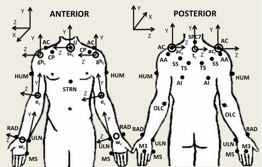 Figure 1: Upper extremity model marker set (Schnorenberg, 2014): suprasternal notch (IJ), xiphoid process (STRN), spinous process at C7 (C7), acromioclavicular joint (AC), inferior angle (AI), trigonum spine (TS), scapular spine (SS), acromial angle (AA), coracoid process (CP), humerus (HUM), olecranon (OLC), radial styloid (RAD), ulnar styloid (ULN), third and fifth metacarpals (M3 and M5). Joint centers: wrist joint center (wc), elbow joint center (ec), glenohumeral joint center (ghc), acromioclavicular joint center (acc), sternoclavicular joint center (scc) and thorax center (tc) are represented by the open circles. Following ISB recommendations, definition of axes of rotation follow right-hand rule and the Z-axis points laterally towards the subject’s right side, the X-axis points anteriorly, and the Y-axis points superiorly (Wu et al., 2005).
 A custom bilateral UE biomechanical model was used for quantitative data collection and analysis (Schnorenberg, 2014). The model consists of 11 segments, including: thorax, clavicles, scapulae, upper arms, forearms and hands. This allows for analysis of the wrists, glenohumeral joints and acromioclavicular joints (three degree-of-freedom) as well as the elbow and sternoclavicular joints (two degree-of-freedom). Twenty-seven passive reflective markers are used to define and track each of the aforementioned segments (Figure 1). The joint axes are embedded at the joint centers which are calculated based on subject specific anthropometric measurements. Euler angle sequences are used to determine the joint angles of the distal segment with respect to the proximal segment (for the shoulder complex, the thorax is proximal to the clavicle, which is proximal to the scapula, which is proximal to the humerus). A Z-X-Y sequence is employed for the wrist, elbow, GH joints and thorax segment and a Y-X-Z sequence is used for the AC and SC joints.
Several key design features were employed by the model to best define shoulder complex kinematics. First, the marker set used to describe the thorax was designed to more closely reflect the model described by Nguyen et al. in which a direct method of marker placement on thorax landmarks reduces the influence of shoulder girdle movement on thoracic kinematic measurements (Nguyen, 2005). To ensure the greatest accuracy when determining the glenohumeral joint center location, regression equations developed by Meskers et al. that employ the positions of five scapula markers was used (Meskers, 1998).
- Additionally, with the inclusion of the scapula segments, a new marker tracking method for the TS and AI scapula markers is used to reduce the effects of skin motion artifact and possible marker-wheelchair interaction, using techniques as developed by Senk et al. (Senk, 2010).
- Body segment parameters, required in the Newton-Euler equations of motion for joint force and moment determination, were calculated through equations developed specifically for the pediatric and adolescent populations. Equations by Jensen et al. (Jensen, 1989) were used to determine the mass of the segment and the location of the segment center of mass, and equations developed by Yeadon et al. (Yeadon, 1989) were applied to determine each segment’s inertias.
A SmartWheel (Mesa, AZ, USA) was used to record the three forces and three moments as applied by the hand to the wheelchair hand-rim during wheelchair mobility. The inverse dynamics method was then used in order to determine the forces and moments at each UE joint of interest through (Zatsiorsky, 2002).
Protocol
Subject recruitment, consent/assent and motion analysis were performed at Shriners Hospitals for Children–Chicago. Six subjects with spinal cord injury (SCI), aged 8 – 18 years (average age: 13 years), were evaluated during manual wheelchair propulsion. The subjects were asked to propel their wheelchairs along a 15 m walkway at a self-selected speed and self-selected propulsion pattern. A 14-camera Vicon MX motion capture system collected the bilateral kinematic data at 120 Hz, while simultaneously a SmartWheel system collected the kinetic data at the hand-handrim interface at 240 Hz. The SmartWheel replaced the wheel on the subject’s dominant side. Four subjects were right hand dominant and two were left hand dominant. Multiple trials were collected with adequate rest allowed between trials.
The GH, AC and SC joint kinematics were determined in all three planes of motion: sagittal, coronal and transverse, except for the SC joint, in which rotation along the long axis of the clavicle is restrained to zero. Additionally, GH joint kinetics were determined along all three axes: medial/lateral, superior/inferior and anterior/posterior. Data was normalized to 100% percent stroke cycle and processed every 1%. The stroke cycle was defined according to Kwarciak et al.’s definition, which not only includes both the contact and recovery phases, but also sub-divides the contact phase into three periods: initial contact, propulsion and release (Kwarciak et al. 2009). Initial contact with the hand-rim, determined through the hand-rim resultant force measurement, marks the beginning of the stroke cycle and the initial contact period of the contact phase, at 0%. The propulsion period begins once a propulsive moment about the axle is detected and transitions to the release period when the propulsion moment ends. The release period ends after the resultant force applied to the hand-rim has dropped below a predetermined threshold (near zero) indicating that the hand is no longer in contact with the hand-rim and transitioning the subject out of the contact phase and into the recovery phase (Kwarciak, 2009). To compare subject data, the forces were normalized to the subject’s body weight (%BW) and the moments were normalized to the subject’s body weight and height (%BWxH). T-tests were used for statistical comparisons.
Results
Spatiotemporal Parameters
The subjects’ transition from contact phase to recovery phase occurred on average (stdev) at 37.0% (6.7%) stroke cycle. The propulsion period of the contact phase occurred on average (stdev) from 4.2% (1.9%) to 35.7% (5.9%). The average (stdev) propulsion speed was 1.3 m/s (0.3 m/s), with a range from 0.8 m/s to 1.7 m/s. It is also interesting to note that while the semi-circular stroke pattern is the recommended pattern for propulsion (Boninger, 2002); only subjects 3, 4 and 6 used this pattern. Subject 1 used more of a single looping over propulsion (SLOP) pattern; subject 2 used a mix between SLOP and double looping over propulsion (DLOP) and subject 5 was very close to an arcing pattern. See Boninger et al.’s work for further detail on propulsion patterns (Boninger, 2002).
Joint Dynamics
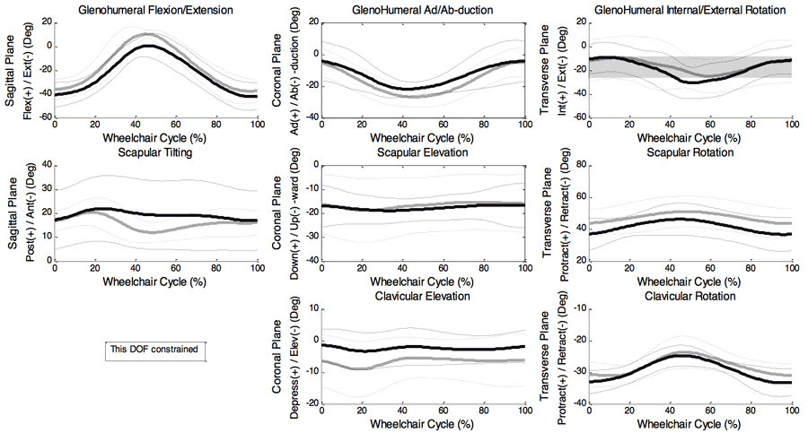 Figure 2: Ensemble average joint kinematic data for 10 stroke cycles of the glenohumeral (GH), acromioclavicular (AC) and sternoclavicular (SC) joints. Mean (bold) and +/- one standard deviation joint kinematics of the GH: top row, the AC joint: middle row, and the SC joint: bottom row. (dominant side: black, non-dominant side: grey)
Mean, +/- one standard deviation (stdev), joint angle curves in each plane of motion were characterized over the wheelchair stroke cycle for the GH, AC and SC joints (Figure 2). T-tests exploring differences between the dominant and non-dominant side peak angles determined the peak GH joint flexion to be a statistically significant difference (p<0.02). The non-dominant side experienced an average peak flexion angle of 13.4 deg (5.9 deg), while the dominant side only experienced 5.1 deg (3.5 deg) of flexion, indicating asymmetry. Additionally, the mean peak GH joint forces along each axis were computed for all six subjects (Figure 3). The average peak forces for the group were 6.5 %BW (2.5 %BW) directed posteriorly, 6.6 %BW (2.5 %BW) directed superiorly and 5.1%BW (3.5 %BW) directed laterally.
Discussion
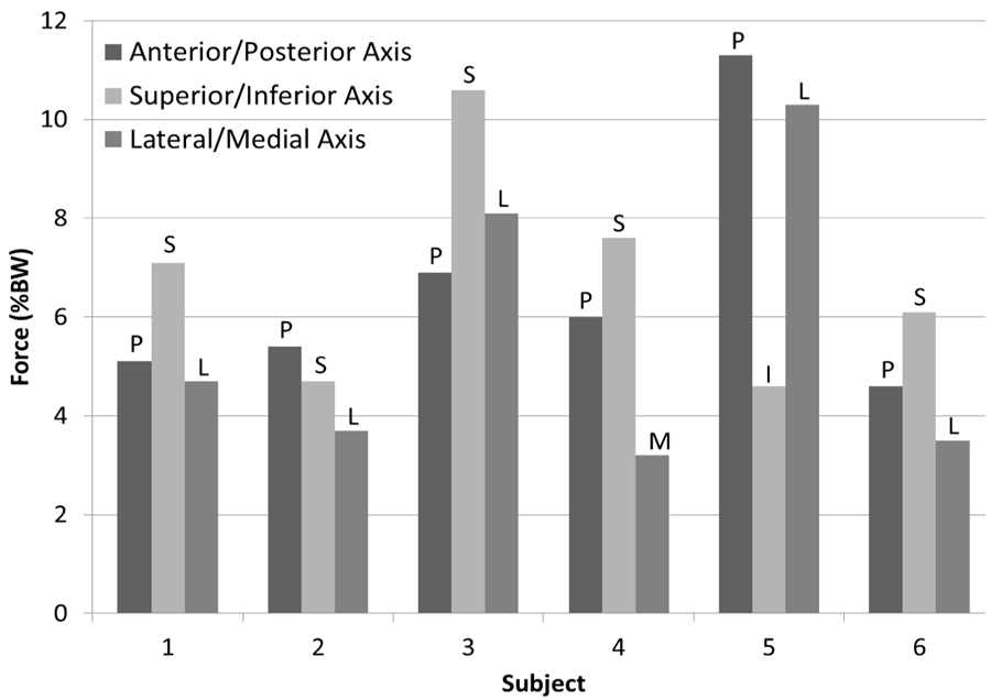 Figure 3: Average peak joint forces for each subject for each axis. The single letter represents the direction of the force.
 At initial contact, the GH joint is extended, slightly abducted and externally rotated. As the subjects move through the stroke cycle the upper arm becomes slightly flexed, showing increased abduction and increased external rotation just after the subject transitions from the contact phase to the recovery phase releasing their hands from the handrim as their hands are furthest forward. Throughout the stroke cycle, the AC joint is posteriorly tilted and shows upward rotation and protracted positioning. The SC joint is elevated and retracted at initial contact, showing a slight increase in elevation as the hand moves over the top of the handrim during the propulsion period, as well as a decrease in retraction until just after the release of the handrim, when the hands are furthest forward. While this general motion mostly agrees with work by Morrow et al. investigating adult MWC propulsion, the scapular tilt did not agree. Morrow et al. found that scapula to be anteriorly tilted, while this study found the scapula to be posteriorly tilted (Morrow, 2011). This may be explained, at least in part, by differences in modeling techniques and subject age. The large standard deviations seen in the ensemble averages suggest that pattern differences may lie within individual subjects and the data should also be analyzed on an individual level.
Only the GH joint peak flexion angle was found to have a statistically significant difference between the dominant and non-dominant sides. Our previous work has shown that, for an individual subject, many more statistical differences are noted between that subject’s dominant and non-dominant sides (Schnorenberg, 2014). The large standard deviations seen in the ensemble average may account for the lack of asymmetry noted in the group. However, one should note the importance of analyzing dominant and non-dominant sides separately, as it has been shown to lead to errors when the sides are averaged together (Boninger, 2002).
Shoulder impingement has been shown to be associated with GH extension, abduction, internal rotation in adults. Additionally, Ludewig and Cook have shown that during arm elevation, adults with shoulder impingement experience a decrease in scapular upward rotation, increased anterior tipping and, under loading conditions, increased scapular medial rotation (Ludewig and Cook, 2000). While under healthy conditions, elevation of the arm is supplemented by scapula retraction, upward rotation and posterior tilt. It is when the scapular and glenohumeral motions are disproportionate that the potential for pain and injury arises (Shamley, 2008). The group of pediatric MWC users evaluated here experience GH extension and abduction as well as scapular protraction throughout most the entire stroke cycle which is concerning for shoulder impingement; however, the scapula also appears to be upwardly rotated and posteriorly tilted during this time. Additionally, in 4 of the 6 subjects, the GH joint experiences its peak force in the superior direction, possibly decreasing the subacromial space and further increasing one’s chances for pain and impingement development. Further investigation, and subject-specific analyses, is warranted to determine which joint positions may be most likely to contribute to shoulder impingement and pain that are commonly developed in MWC users.
Other factors that may have accounted for the variability seen here are the differences in stroke patterns used, and the large range in self-selected propulsion speeds. These factors, along with age, SCI level and time of device use should be further investigated.
conclusion
Our custom biomechanical model successfully quantified the 3D joint kinematics of the GH, AC and SC joints, as well as the 3D GH joint kinetics. The data suggests subject specific evaluation may be required as well as investigation into other possible influential factors such as subject age, SCI level, etc. A greater understanding of the biomechanics of the shoulder complex should assist in identification of risk factors leading to pain and pathology development in pediatric MWC users and thus improved clinical guidelines, training and rehabilitation.
References
Boninger, M.L., Souza, A.L., Cooper, R.A., Fitzgerald, S.G., Koontz, A.M., Fay, B.T. (2002). Propulsion patterns and pushrim biomechanics in manual wheelchair propulsion. Archives of Physical Medicine and Rehabilitation, 83, 718–723.
Brault, M.W. (2012). Americans with disabilities: 2010. Current Population Reports, Washington, DC: US Census Bureau, pp. 70-131.
Jensen, R.K. (1989). Changes in segment inertia proportions between 4 and 20 years. Journal of Biomechanics, 22, 529–536.
Ludewig, P.M., and Cook, T.M. (2000). Alterations in shoulder kinamtics and associated muscle activity in people with symptoms of shoulder impingement. Phys Ther, 80, 276-291.
Meskers, C.G., Van der Helm, F.C., Rozendaal, L. a, Rozing, P.M. (1998). In vivo estimation of the glenohumeral joint rotation center from scapular bony landmarks by linear regression. Journal of biomechanics, 31, 93–6.
Morrow, M.B., Kaufman, K.R., An, K.N. (2011). Scapula kinematics and associated impingement risk in manual wheelchair users during propulsion and a weight relief lift. Clinical Biomechanics, 26, 352-357.
Nguyen, T.C., Baker, R. (2004). Two methods of calculating thorax kinematics in children with myelomeningocele. Clinical biomechanics, (Bristol, Avon), 19, 1060–1065.
Schnorenberg, A.J., Slavens, B.A., Wang, M., Vogel, L., Smith, P.A., Harris, G.F. (2014) Biomechanical model for evaluation of pediatric upper extremity joint dynamics during wheelchair mobility. Journal of Biomechanics. 47, 269-276.
Šenk, M., Chèze, L. (2010). A new method for motion capture of the scapula using an optoelectronic tracking device: a feasibility study. Comput methodsbiomech biomed engin, 13, 397–401.
Shamley, D., Srinaganathan, R., Oskrochi, R., Lascurian-Aguirrebena, I., Sugden, E. (2008). Three-dimensional scapulothoracic motion following treatment for breast cancer. Breast Cancer Res Treat, 118, 315-322.
Wu, G., et al. (2005). ISB recommendation on definitions of joint coordinate systems of various joints for the reporting of human joint motion - Part II: shoulder, elbow, wrist and hand. Journal of Biomechanics, 38, 981–992.
Yeadon, M.R., Morlock, M. (1989). The appropriate use of regression equations for the estimation of segmental inertia parameters. Journal of Biomechanics, 22, 683–689.
Zatsiorsky, V.M. (2002). Kinetics of Human Motion. Champaign, IL: Human Kinetics.
Acknowledgements
The contents of this work were developed under a grant from the Department of Education, NIDRR grant number H133E100007. However, the contents of this work do not necessarily represent the policy of the Department of Education, and you should not assume endorsement by the Federal Government.
Audio Version PDF Version