Modelling And Simulation Of Lower Extremity Powered Exoskeleton
Brandon Fournier1, Andrew J.J. Smith2, Marc Doumit2,3, Edward D Lemaire1,2
1The University of Ottawa, Ottawa-Carleton Institute for Biomedical Engineering
2The Ottawa Hospital Research Institute
3University of Ottawa Department of Mechanical Engineering
Abstract
Lower extremity powered exoskeletons (LEPE) allow people with spinal cord injury to stand, walk, and perform activities of daily living. Unfortunately these assistive devices walk slowly and may cause user fatigue if forearm crutches are overused. This underscores the need to gain greater understanding of LEPE requirements and to improve LEPE design. This research modelled the ARKE LEPE (Bionik Labs) using the Anybody musculo-skeletal modelling software. In this case very slow walking marker data was used to drive the kinematics of the human-LEPE model and correlations between predicted ground reaction forces (GRF) and real force plate data were calculated and found to be significant for all speeds. Vertical GRF had the strongest correlations while transverse had the lowest. The strong correlations suggest that a validated model can be used to determine optimal biomimetic LEPE joint mechanics to improve LEPE design.
Background
Lower extremity powered exoskeletons (LEPE) allow people with spinal cord injury to stand, walk, and perform activities of daily living. Unfortunately these assistive devices walk slowly and may cause user fatigue if forearm crutches are overused (Lal, 1998; Louie, Eng, & Lam, 2015; Talaty, Esquenazi, & Briceno, 2013). Several approaches can be taken to improve understanding of biomimetic requirements for LEPEs and LEPE design. The typical engineering approach is to create simple analytical models and make good guesses to guide initial prototype design, and then iteratively build new prototypes that improve on design. Others have built exoskeleton and prosthetic emulators that use larger actuators tethered to the device to deliver a wide range of force outputs that simulate a wide range of possible design mechanics. This approach has the advantage of measuring real human reaction (Witte, Zhang, Jackson, & Collins, 2014). Virtual prototyping (computer simulations) can also be used to measure optimal mechanical requirements, taking LEPE-human interactions into account, and can be more cost effective and time efficient.
Few studies have been published on LEPE simulations. One study compared joint moments with and without a real LEPE using OpenSim; however, this simulation did not take ground reaction forces (GRFs) into account (Ferrati, Bortoletto, & Pagello, 2013). A study using the Anybody modelling software (AMS) presented a full body powered exoskeleton model (BLEEX for lower body and ABLE for upper limbs) and compared the effect of straps on human joint torque and interaction forces between the human and the LEPE for different activities including walking at normal speed (Cho, Kim, Jung, & Lee, 2012). A number of other exoskeleton simulation studies focus on partial assist devices and measure the unloading of biological muscles (P. Agarwal, Kuo, Neptune, & Deshpande, 2013; Priyanshu Agarwal, Narayanan, Lee, Mendel, & Krovi, 2010; Guan, Ji, Wang, & Huang, 2016).
Although these studies are interesting, research is lacking for models or simulations of a real LEPE performing realistic LEPE walking (very slow) and validation of the results.
This research presents a human-LEPE musculoskeletal model implemented in AMS. GRFs predicted using the human-LEPE model, driven by three dimensional healthy slow walking data, were compared to healthy slow walking GRF data measured using force plates. Strong correlations between predicted GRF and force plate GRF data would suggest that a validated model could be used to determine optimal biomimetic LEPE joint mechanics and thus improve LEPE design.
Methodology
Participants
A convenience sample of five healthy people (170.8±8.6cm, 70.7±10.6kg) volunteered to walk at four slow speeds: 0.2 m/s, 0.4 m/s, 0.6 m/s, and 0.8 m/s on a CAREN-Extended system (6-DOF movable platform with dual force plate instrumented treadmill and Vicon motion capture system). Full body kinematic data were sampled at 100Hz. Force plate data were sampled at 1000Hz. The slow speeds accurately represented possible LEPE motion. Results were computed from ensemble averages of 10 strides, for each participant.
Musculo-skeletal Model
The anybody GaitFullBody (GRB) model was used for the model’s human component. This model contained 37 bone segments and 69 degrees-of-freedom (DOF), including 3 at the hips, 1 at the knee, and 2 at the ankle (plantar/dorsiflexion,inversion/eversion). Lower extremity muscles were removed from the model to simulate paraplegia.
LEPE Model
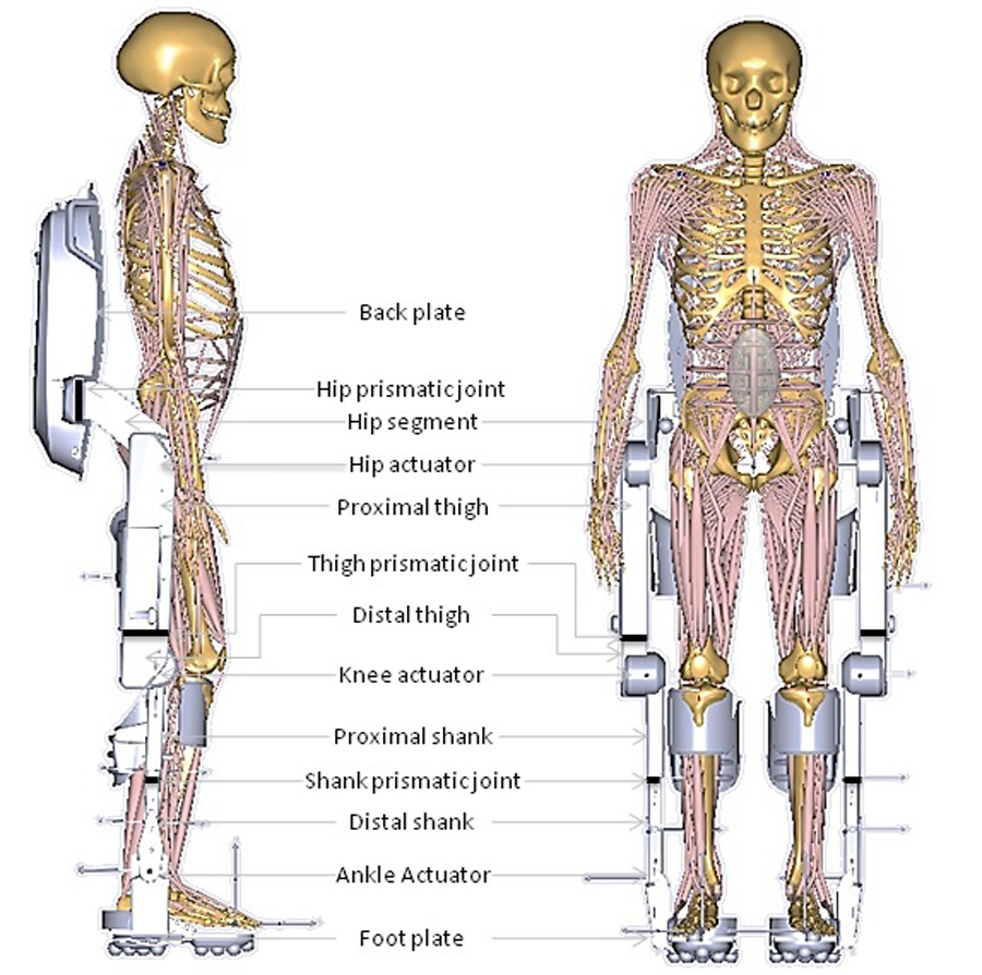
LEPE joint moments were provided by AnyGeneralMuscle objects with specified maximum strength and applied forces from an Anybody muscle recruitment optimization algorithm. AnyGeneralMuscle strengths were optimized to be as small as possible without overloading and to ensure sagittal plane GRFs point through or near LEPE joints.
LEPE-Human-Environment Interaction
The LEPE was kinematically constrained to the human at the pelvis in all 6 DOF (with LEPE and human hip joints aligned), at each foot in all DOFs, and the LEPE and human knee joint anterior-posterior positions were aligned. Constraints at the pelvis and knees were set to “soft” to allow some relative motion and to accommodate for a model that was kinematically over-constrained. Since the combined human-LEPE centre-of-mass (COM) was slightly posterior and inferior to the human-only COM, a correction was made at the ankles to bring the COM forward to its original position. The ankle was chosen since this is the most efficient way to correct COM position for small variations (Runge, Shupert, Horak, & Zajac, 1999). The average dorsiflexion correction was 2.30o (±0.34).
Interaction forces between the LEPE and the human were applied with AnyGeneralMuscles that acted in every DOF between LEPE foot and human foot, as well as every DOF except axial force at the shanks, thighs, and pelvis.
Since inertial properties of the combined system were different from the human alone, human-only force plate data was replaced by Anybody’s conditional contact force-plate model. Virtual muscle actuators located at nodes under the LEPE feet were included in the muscle force optimization algorithm, and active when these nodes were determined to be in contact with the ground. 160 nodes were placed under each foot, with a higher density near the toe region and with nodes forming a curved pattern, to better simulate rollover at terminal stance and obtain smoother and more biological ground reaction forces. Speed and height criteria were used to determine when nodes were in contact with the ground contact cylinder. From a preliminary sensitivity analysis, the speed threshold was a function of gait speed. The height threshold and node muscle strength were modified for each participant to remove discontinuities in ground reaction force while minimizing “hand-of-God” residual pelvis forces (which accounted for errors between GRF and inertial properties).
Model performance was evaluated with Pearson-correlation and root-mean-square error (RMSE) of GRF between model predicted and force plate data.
Results
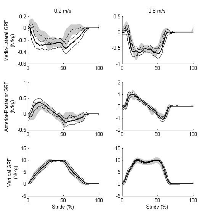
Table 1: Average Pearson-correlation (r) and RMSE (N/kg) between predicted and measured GRF for different speeds (v) (m/s). SD in ().
| v | Medio-Lateral GRF | Anterior-posterior GRF | Vertical GRF | |||
|---|---|---|---|---|---|---|
| r | RMSE | r | RMSE | r | RMSE | |
| 0.2 | 0.65 (0.16) | 0.14 (0.05) | 0.84 (0.12) | 0.10 (0.03) | 0.99 (0.00) | 0.33 (0.07) |
| 0.4 | 0.85 (0.07) | 0.14 (0.05) | 0.91 (0.03) | 0.13 (0.03) | 0.99 (0.00) | 0.25 (0.06) |
| 0.6 | 0.91 (0.05) | 0.14 (0.06) | 0.94 (0.03) | 0.15 (0.04) | 0.99 (0.00) | 0.33 (0.11) |
| 0.8 | 0.93 (0.04) | 0.13 (0.04) | 0.96 (0.01) | 0.16 (0.03) | 0.99 (0.00) | 0.37 (0.09) |
Discussion and Conclusion
As was the case in a study validating the Anybody conditional contact model (Fluit, Andersen, Kolk, Verdonschot, & Koopman, 2014), the predicted vertical GRF had the strongest correlations to force plate data, followed by anterior-posterior GRF, and transverse GRF having the lowest correlation. Authors of this study proposed that this was due to an over-constrained knee model that did not include transverse rotation.
The lower correlations for slower walking speeds are likely due to longer double support times (DST). Longer DST leads to a greater potential for error since this is a statically indeterminate case that depends on the Anybody muscle recruitment algorithm to determine the share of GRF and GRM between both legs in contact with the ground.
In general, correlations between predicted GRF of users wearing the LEPE versus actual force plate GRFs of participants without the LEPE were surprisingly high, despite changes in inertial properties. In fact, correlations were higher than those found in (Fluit et al., 2014). This could be due to correlations being computed on ensemble averages, a longer percentage of the gait cycle, or perhaps the modified foot node configuration improved results during DST.
Several limitations in the model should be noted. A full validation is required, comparing predicted GRFs to actual force plate data recorded while the participant wears the LEPE. A rigorous sensitivity analysis of predicted GRF model parameters and their effect on predicted GRF is also required. Furthermore, it was assumed that healthy walking kinematics of individuals not wearing a LEPE were also optimal for individuals wearing a LEPE. The model partially mitigates this problem by correcting A-P COM position; however, inertial properties between an individual without a LEPE and an individual with a LEPE are different, which would lead to different natural dynamics and thus potentially different optimal walking kinematics. However, the high correlations presented in this paper suggest that inertial changes may not be an important factor, implying that using biomimetic kinematics to determine optimal LEPE mechanics may be appropriate.
Future studies using this model will measure LEPE joint mechanics needed to reproduce healthy motion.
References
Agarwal, P., Kuo, P. H., Neptune, R. R., & Deshpande, A. D. (2013). A novel framework for virtual prototyping of rehabilitation exoskeletons. In 2013 IEEE 13th International Conference on Rehabilitation Robotics (ICORR) (pp. 1–6).
Agarwal, P., Narayanan, M. S., Lee, L.-F., Mendel, F., & Krovi, V. N. (2010). Simulation-Based Design of Exoskeletons Using Musculoskeletal Analysis, 1357–1364.
Cho, K., Kim, Y., Jung, M., & Lee, K. (2012). Analysis and evaluation of a combined human - exoskeleton model under two different constraints condition. Proceedings of the International Summit on Human Simulation, 1–10.
Ferrati, F., Bortoletto, R., & Pagello, E. (2013). Virtual Modelling of a Real Exoskeleton Constrained to a Human Musculoskeletal Model. In N. F. Lepora, A. Mura, H. G. Krapp, P. F. M. J. Verschure, & T. J. Prescott (Eds.), Biomimetic and Biohybrid Systems (pp. 96–107). Springer Berlin Heidelberg.
Fluit, R., Andersen, M. S., Kolk, S., Verdonschot, N., & Koopman, H. F. J. M. (2014). Prediction of ground reaction forces and moments during various activities of daily living. Journal of Biomechanics, 47(10), 2321–2329.
Guan, X., Ji, L., Wang, R., & Huang, W. (2016). Optimization of an unpowered energy-stored exoskeleton for patients with spinal cord injury. In 2016 38th Annual International Conference of the IEEE Engineering in Medicine and Biology Society (EMBC) (pp. 5030–5033).
Lal, S. (1998). Premature degenerative shoulder changes in spinal cord injury patients. Spinal Cord, 36(3), 186–189.
Louie, D. R., Eng, J. J., & Lam, T. (2015). Gait speed using powered robotic exoskeletons after spinal cord injury: a systematic review and correlational study. Journal of NeuroEngineering and Rehabilitation, 12(1), 1.
Runge, C. F., Shupert, C. L., Horak, F. B., & Zajac, F. E. (1999). Ankle and hip postural strategies defined by joint torques. Gait & Posture, 10(2), 161–170.
Talaty, M., Esquenazi, A., & Briceno, J. E. (2013). Differentiating ability in users of the ReWalkTM powered exoskeleton: An analysis of walking kinematics. In 2013 IEEE International Conference on Rehabilitation Robotics (ICORR) (pp. 1–5).
Witte, K., Zhang, J., Jackson, R., & Collins, S. (2014). Design of Two Lightweight, High-Bandwidth Torque-Controlled Ankle Exoskeletons. Proceedings of the IEEE International Conference on Robotics and Automation (ICRA), 1223–1228.
Acknowledgements
The authors acknowledge financial support from Ontario Centres of Excellence and Bionik Laboratories.