Riley Desserre, Angelene Fajardo, Joseffus Santos
University of ManitobaProblem Statement/Research Question and Background
Currently, people with fine motor control difficulties are unable to utilize many technologies due to the high cost of available solutions. To democratize accessibility, open-source general solutions must be pushed forward that can be made by anyone with minimal expertise or adapted for normal manufacturing. Accessibility products rarely reach mass market appeal and often have far more development costs to unit sold which can be spread out by crowdsourcing development.
The client for this project is a younger individual with difficulties in fine motor control in most appendages with the neck or head being the most suitable control interface. The initial intent was to deliver a device that would enable them to play with friends or family on Xbox games for a price matching a high-end gaming mouse ($100 USD) to undercut other solutions that are many hundreds of dollars.
Methods/Approach/Solutions Considered
The following approaches and methods were considered to solve the design problems. Their associated advantages and disadvantages are used to determine the efficiency and compatibility of the methods.
Off The Shelf Controller/Gyroscope on Head Mount
The use of an off-the-shelf gyroscope attached to a head mount is beneficial with respect to minimal design of PCB, which requires a smaller skillset to make and build. Additionally, if an individual has a controller for various gaming consoles, they will have access to a gyroscope, ensuring that calibration routines would be built-in to the component. In contrast, the use of this method may not be cost-efficient due to its wide range of features not utilized for the purpose. The use of an off-the-shell gyroscope also raises compatibility concerns depending on where it is sourced and applied.
Head Camera Tracking (Tracking using webcam and software)
The head camera tracking method uses software and a webcam to track the head movements of a person. An advantage of this design is that it would accommodate a wide range of audiences as it is governed by software. Additionally, it is lightweight making it easy to mount. This method is also accompanied by more design development rather than research to determine efficient tracking. This raises concerns with processing issues for accuracy, speed, and complexity of camera calibration. This would also require more time and setup prior to usage.
As mentioned in the previous paragraph, since the head camera tracking method uses software, it will be easily accessible for immediate use. In this way, we can allocate more time for development of the software to improve the accuracy of the tracking rather than starting the program from scratch. The head tracking camera will be lightweight so it can sit comfortably on the head of the person and make head movements effortless. Moreover, the camera can be easily mounted to the head of the person and this method will be accessible for most people.
Infrared Remote Tracking on Head Mounting
Infrared remote tracking was considered for this design but was not chosen to be implemented. Using an infrared device would have allowed for easier calibration, but the concerns outweigh the benefits. Infrared remote tracking is not as accessible as less research and resources are available for this use. Using infrared also allows for background interference from bright lights which can impact gameplay, and the signal can be physically blocked by common household objects.
Custom Gyroscope on Head Mount
The final hardware solution that was implemented for this design is a head mounted custom gyroscope. Though this solution was more complex than others, and required the team to build it from scratch, the benefits outweigh the concerns. Since this solution will be fully customizable, the overall system can be adapted for a very specific use to match the user's liking. This solution will not have interreferences like the infrared option, as it is dependent on head movement, not light.
Clamshell Design (Enclosure Section)
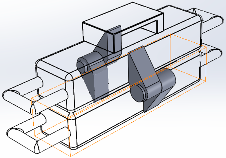
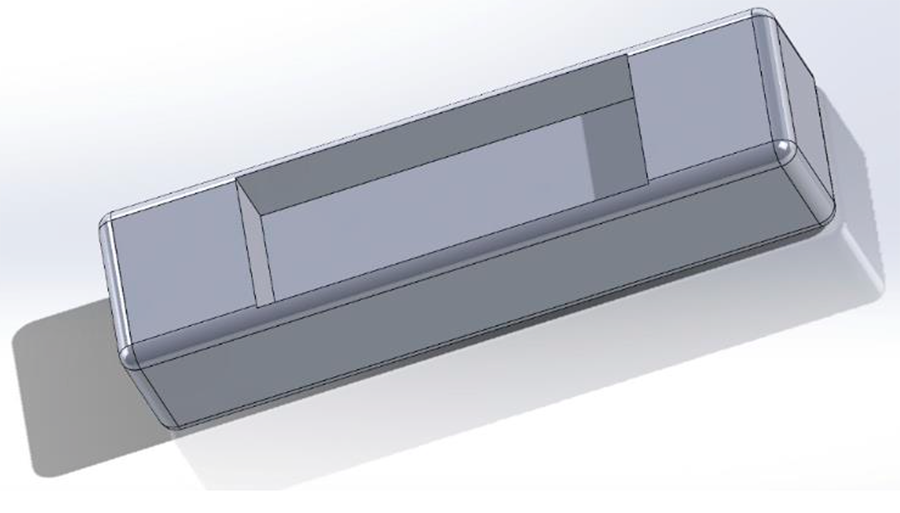
The enclosure design is analogous to a clamshell. It has a top and bottom part which have an offset to house the CPU and the sensor. The top and bottom part have similar dimensions so that they can fit together and hold the sensor and the CPU in a rigid fashion. We have chosen a hinge mechanism for holding the top and bottom part together for simplicity and to allow easy access to the CPU and sensor if they need to be replaced.
Overall, the enclosure will be lightweight to provide a comfortable experience to the user as it will sit on the head of a person via an elastic band. However, even if the enclosure is lightweight, it will have a rigid structure so that it does not break if it were to fall or slip from the user's head. We will 3D print our prototype as this method is inexpensive compared to other printing processes such as laser printing.
Elastic band
The elastic headband recommended for the enclosure must have a 1-inch width with an inner 10.5-inch non-slip silicone strip to prevent sweat from flowing into the eyes. The elastic headband should be comprised of two headbands: a top headband with a minimum length of 11.4 inch and a circumference headband with a minimum length of 26.5 inch. This is to make sure that both headbands can be used together to ensure that the enclosure is snug and will be able to fit all head shapes.
T-shaped Shell Design
The T-shaped design is difficult to implement due to strength considerations both from the attachment of the sensors and the durability concerns from 3D printing. This also forms issues with cord management due to the nature of the design. In contrast, some benefits to this design are that it ensures sensors do not contact one another and that it allows for easy attachment to a head piece.
Description of final approach and design
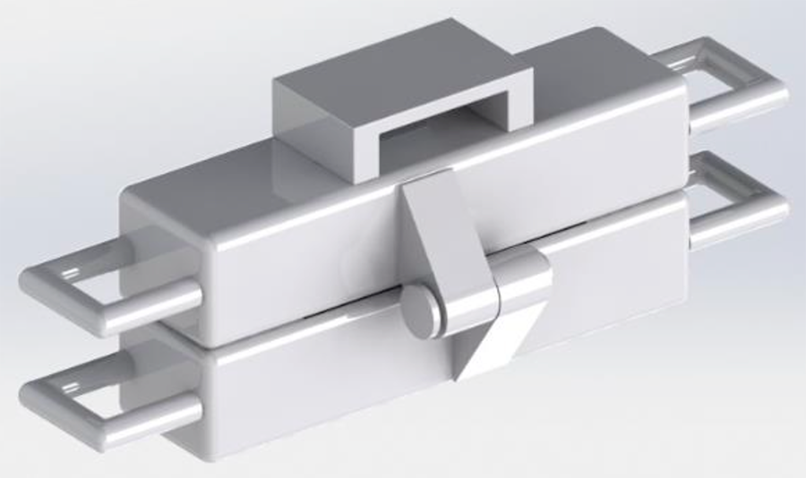
The final design for the enclosure is a 3D printed design that houses the Raspberry Pi and sensor. The enclosure is a rectangular shape with cut-outs for the hardware components to nestle into, with optimal space between the two cut-outs.
The enclosure has hooks on the sides and top to allow for the elastic head band to secure onto the enclosure. The hinges and pins are what hold the enclosure together, this method eliminates the need for screws. By using hinges as opposed to screws, it minimizes the complexity of the design and the number of components the manufacturer would be required to purchase. To mount the enclosure onto the head of the user, an elastic headband similar to the ones attached to a headlamp will be used. This was chosen as the final design due to its accessibility, adjustability, and comfort level.
The Raspberry Pi (RPI) Pico was chosen since it provides a low-cost platform with superior processing capabilities compared to other microcontrollers in a similar cost bracket. Compared to the popular 8-bit 16MHz microcontrollers used in hobbyist rapid prototyping. The Raspberry Pi Pico allows the use of a dual core cortex M0 processor running at 133MHz. Multiple processors allow us to run tasks concurrently. Polling gyroscope data can be run while previous cycle data is being processed. 264KB of SRAM and 2MB of onboard flash allow us to store user settings and calibration information between power cycles. Our current design utilizes a GY-521 breakout board with an on board MPU 6050 6-DOF gyroscopes to gather 3 axis orientation and 3 axis acceleration data. The MPU 6050 was chosen since this gyroscope has multiple libraries available which would speed up the development process. The MPU 6050 communicates with the RPI Pico using the I2C protocol. Gyroscopes that communicate via I2C are more cost effective than their SPI counterparts. Our design would attempt to work within the limitations of I2C to produce a viable gyroscope-based joystick. Our choice of the RPI Pico platform would allow us to improve upon our design in the future with faster gyroscopes and additional degrees of freedom for better drift correction.
The software uses a USB library to emulate a generic USB gamepad. This allows our device to be used with any PC or MAC device. We also allow compatibility with Microsoft Xbox via the Xbox adaptive controller (XAC). XAC was developed to allow easy development of non-standard game controllers for gamers with disabilities. We designed our system to be compliant with USB power specifications to allow our device to be safely powered from any USB port on a PC or through the XAC.
There are multiple programming options available for the Raspberry Pi Pico. These include RPI MicroPython SDK, official RPI C++ SDK and Arduino Mbed core. We chose a Realtime Operating system (RTOS) based on the open source Mbed OS. The Mbed Arduino core for the Raspberry Pi Pico exposes both Arduino standard library functions and Mbed functions. Open-source libraries allow us to better understand the actual implementation of functions and allow us to modify them to better suit our needs. An RTOS was chosen to take full advantage of the dual cores of the Raspberry Pi Pico. We use one core for polling the gyroscope and the other core to handle data processing and translation into standard USB gamepad output. Since there are plenty of open-source libraries that already implement protocols for polling the chosen gyroscope we simply had to verify that the library matched the commands required in the datasheet. We used an open-source library that sends the correct USB parameters to the host PC to identify our device as a generic USB gamepad. These choices allowed our software developers to focus on data processing methods to ensure a good user experience. These include functions for calibration, error correction, outlier rejection. Due to our choice of OS, most of our code was written in C++. We followed standard object-oriented approaches to allow us to update and modify our code easily in the future.
Outcome (Results of any outcomes testing and/or user feedback)
The design has met all objectives in terms of cost, weight, user accessibility and adaptability. The goal of having the device be less than 50g has been met. The device includes 6g of hardware and a 30g 3d printed enclosure. Another objective of the design was to have the cost to be under $100 USD. The cost outcome is approximately $20 USD, which is significantly lower than the set limit. The design is easily accessible and adaptable to enhance user experience. The user can plug in and play using any device that can take a generic USB. The design can be easily expanded or adapted upon as the user can change the platform/chip used and/or the specific type of gyroscope used.
To maximize user function and experience we plan to make further iterations of the design, specifically to improve mounting stability and device calibration. Device calibration is a frequent cause of user concerns due to inconsistent mounting and/or gyroscopic drift. In later iterations, we plan to have more advanced calibration functions or secondary sensors to cross-reference any movement data. The stability of the device may be a user concern. In later iterations, the mounting may need to be revised as the current mounting solution has difficulties constraining movement in z-direction. The mount currently has two points of contact stabilizing it in the x and y direction only.
Cost (to produce and expected pricing)
Item |
Cost |
Raspberry Pi Pico |
$4.00 |
GY-521 |
$4.00 |
Generic USB C to USB C adapter |
$5.00 |
Generic USB C to USB C cable (10 ft long) |
$5.00 |
Manufacturing costs |
$5.00 |
Significance
For those with fine motor control difficulties, it can be difficult to navigate technology using traditional input devices. Head tracking devices offer an accessible solution for consumers that have head and neck control. Unfortunately, the solutions that are currently available are not financially accessible for all consumers: one example is the GlassOuse head mouse, which costs $599 USD [1]. The GlassOuse also requires a Bluetooth connection, which severely limits its range of compatible devices.
The Gaming Head Mouse provides a cost-effective alternative at an approximate price of $20 USD. It connects via USB, allowing plug-and-play experience with most computers. The device can also interface with the Xbox Adaptive Controller for gaming on the Microsoft Xbox console. Since the code is open source, the device can be made by anyone. Those looking to make the device themselves require only a few low-cost, off-the-shelf components. The design uses the widely available Raspberry Pi Pico, along with a common GY-521 gyroscope, and a USB-C cable and adapter that many users may already own. The system also allows for easy customization if customers have more specific concerns. Due to the modular code structure, future manufacturers can easily adapt the code for use with different components.
Acknowledgements
We would like to thank the University of Manitoba and our generous sponsors for their support and encouragement throughout this project, as well as Nishant Balakrishnan for his lab and supervisory assistance.