INNOVATIVE COMPUTER INPUT DEVICE FOR DISABLED PEOPLE
ABSTRACT
A computer user traditionally controls the movement of a screen pointer using a standard point and click mouse; however, some individuals who have poor to no hand or finger movement or are totally disabled cannot use standard input devices. Alternative input devices are required to provide similar functionality to these individuals. Such devices come in many different shapes and sizes to accommodate a variety of limitations. This paper reports on an innovative intra-oral input device; its major advantages being user comfort and ease of use. This intra-oral device requires a tongue to control cursor movement, a puff to simulate a right mouse click and a bite on a switch to simulate the left mouse click.
BACKGROUND
There are many commercially available alternative input devices that can replace the traditional mouse. These devices may be activated using an individual's foot, head, eye, mouth, breath, hand, thumb, or a single finger (1). Some of these devices require individuals to sit upright and possess fine motor skills such as head rotation. Someone who has lost his or her ability to speak and has no reliable motor-movement below the neck will require other special devices. There are three existing commercial devices that can provide partial solutions to address this problem. The first involves wearing a headband that collects surface electrical signals from the brain and subtle muscle activity and processes these into commands to move the pointer (2). The second device tracks eye pupil movements (3). The third device has a switch operated mini frequency modulated (FM) transmitter embedded inside a custom fitted denture-like device. The tongue closes a number of switches whose status is decoded by an FM receiver and used to control devices. The feedback from users of these devices is that they are difficult to operate and are not comfortable to use. Currently, there is work being done in the field of Functional Electrical Stimulation (FES) that involves surgically implanting cortical electrodes. Brain signals are used to directly stimulate a muscle function or to control an assistive device; unfortunately it is expected that the cost of surgery and the supported equipment will be prohibitive, which will prevent this solution from becoming generally available.
RESEARCH QUESTION
The objective of this research is to determine the feasibility of developing an innovative computer input device for use by the disabled that is comfortable, easy to use, and low cost.
METHOD
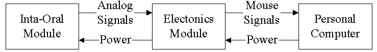
The designed innovative computer input device consists of an intra-oral module and an electronics module. Figure 1 shows a block diagram of the device. The intra-oral module will be placed inside of the mouth, and the electronic module will be placed close to a computer. The signals from the intra-oral module will be converted to mouse function signals by the electronic module. Both modules consume very little power and receive their power from the computer.
 |
Intra-Oral Module
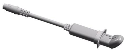 |
The intra-oral module consists of four Hall Effect sensors coupled with four magnets, a single air pressure sensor and a single push button switch. The four magnets are permanently embedded in a moveable plate, which is attached to the main body of the device through a post. The four corresponding Hall Effect sensors detect the movement of the plate (in particular the magnets) toward and away from each sensor. The tongue is used to move this plate, much like a joystick. These movements are converted to direction and speed data, and cause the on-screen pointer to move. For `return-to-center' feedback, a rubber bumper is attached to the base of the post. The pressure sensor is used to detect the puff and sip actions. The puff simulates a right mouse button event, and the sip event is configurable. Lastly there is a bite table, which is connected to a push button that can detect a biting event. This simulates a left mouse button click. The length of the intra-oral module is adjustable so that it fits comfortably into the mouth. Figure 2 depicts the intra-oral module.
Electronic Module
 |
The electronic module consists of a microcontroller, power control circuitry and interface circuitry. Signals from the intra-oral module are converted to mouse signals that are compatible with a personal computer. The electronic module is connected to a computer via a PS/2 connection. In addition to the mouse functionality, several banks of ports are provided which allow for the control of other equipment. Also, the electronics module can be calibrated and controlled through a serial port connector.
RESULTS
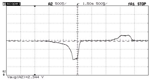
A prototype intra-oral module was developed to verify the interface functionality with the user. The intra-oral module consumes a maximum of 28mA when it is activated and zero power while it is deactivated. Figures 3, 4 and 5 show the output signals from a Hall Effect sensor while the moveable plate was cycled through its range, a sip and puff action on the air pressure sensor and a biting action on the switch.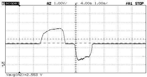 |
 |
CONCLUSION
The prototype intra-oral module was developed and the results demonstrated that all the embedded sensors and switches function properly. It fits comfortably in the mouth and is easy to operate. The next two stages of this project are the refinement of the prototype and electronics module, and the start of clinical trials.
REFERENCES
- Web page http://janweb.icdi.wvu.edu/media/altinput.html
- Pfurtscheller G., Flotzinger D., and Kalcher J. (1993). Brain-Computer Interface - a new communication device for handicapped persons, J Microcomp Appl, 16: 293-299.
- Web page http://orin.com/index.htm
ACKNOWLEDGMENTS
This research and development was financially supported by the Industrial Research Assistance Program, National Research Council, Government of Canada, and Mr. Peng Fong Mok. Special thanks are given to the Innovation Center, Edmonton Capital Region, Alberta, Canada.
Dr.
Edmond Lou, Mr. Mark Fedorak
Xanantec Technologies Inc.,
#200, 17612-107 Ave
Edmonton, Alberta, Canada T5S 1G8
Ph: (780)
421-9181
elou@xanantec.com
mfedorak@xanantec.com
Mr.
Kelvin Mok
MOK Products Corp.,
997 Knottwood Road South
Edmonton, Alberta, Canada T6K 3X4
Ph: (780) 463-4099,
klmok@shaw.ca
Mr.
Chris Kirchen
Three Apples Design Inc.,
4465-99 Street,
Edmonton, Alberta, Canada T6E 5B6
Ph: (780) 432-3920,
tadesign@telusplanet.net