EFFECT OF UNIVERSAL DOCKING INTERFACE GEOMETRY (UDIG) PLACEMENT ON WHEELCHAIR AND OCCUPANT KINEMATICS
ABSTRACT
A Universal Docking Interface Geometry (UDIG) has been under development to enable independent wheelchair securement (docking) for all WMD users traveling in motor vehicles [1]. Wheelchair and occupant kinematics during frontal (30mph/20g) and side (15mph/12g) impact were investigated for various attachment locations of the UDIG. Computer simulations were conducted with a manual wheelchair model and a 50th percentile Anthropomorphic Test Dummy (ATD). Wheelchair center of gravity (CG) and UDIG placement were systematically altered and their effect on horizontal (fore/aft), vertical and lateral displacement of the wheelchair (at the P-point) and occupant (head and knee) were measured. Simulation results show that occupant and wheelchair excursions stayed well within ISO excursion limits. Excursions were minimized when the UDIG was mounted wide and forward on a low-CG wheelchair, and when the UDIG was grasped high.
BACKGROUND
 |
 |
RESEARCH METHOD
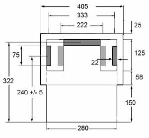
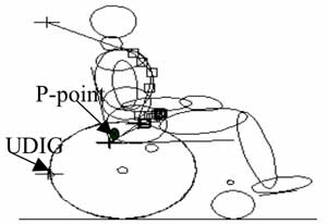
Computer simulations were conducted using Dynaman version 4.0 and a validated model of a standard manual wheelchair (46 lb.). A 50th percentile male Hybrid III ATD was used to represent the wheelchair occupant [5]. The occupant was restrained with a wheelchair mounted pelvic belt and a vehicle mounted shoulder belt. Figure 2 shows the wheelchair model and figure 3 the ranges of location of the UDIG adaptor, i.e. fore/aft position, height position (w.r.t. the floor of the vehicle), and width along the centerline.
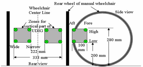 |
Frontal impact was simulated using a 30mph/20g, and side impact was simulated using a 15mph/12g sled pulse [6, 7]. Since wheelchair CG can affect wheelchair and occupant kinematics, the CG was systematically altered from a 12 in. (low) to 17.5 in. (high) above the vehicle floor for the various simulation trials [8, 9]. The variables measured were horizontal (X) displacement, vertical (Z) displacement, and lateral (Y) displacement of the ATD's head, knee and wheelchair P-point (see Figure 2). Lateral displacement of the wheelchair (@ the P-point) was measured during side impact trials only. Excursion measurements during frontal impact were recorded during forward motion only.
RESULTS
Simulation results of wheelchair and occupant forward (X-dir) and vertical (Z-dir) excursions due to frontal impact for the various UDIG locations are listed in Table 1. Table 1 also lists the excursion limits from ISO-10542 for wheelchair, head and knee for frontal impact. Simulation results of lateral (Y-dir) and vertical (Z-dir) excursions due to side impact are listed in Table 2. Excursion limits for side impact are yet not available in current wheelchair standards.
CONCLUSIONS
For all proposed UDIG adapter placements, forward wheelchair and occupant excursions remained within the ISO limits. Wheelchair and occupant kinematics stayed well within the excursion limits for frontal impact when placing the UDIG on a manual wheelchair. During frontal impact the configuration to minimize wheelchair head and knee excursions is a high, wide and forward mounted UDIG adapter for wheelchairs having a low CG. A wide mounted UDIG adapter is necessary to minimize vertical and lateral wheelchair excursions during side impact. Fore and aft UDIG adapter locations did not show large differences in wheelchair, head or knee excursions. Future research will evaluate wheelchair and occupant excursions due to UDIG placement on power wheelchairs and scooters.
REFERENCES
-
Van Roosmalen, L. and D.A. Hobson. Issues related to the location of a universal interface for automated wheelchair securement. RESNA annual conference. 2002. Minneapolis, MN: RESNA Press.
-
Hardin, J.A., C.C. Foreman, and L. Callejas, Synthesis of securement device options and strategies. 2002, National Center for Transit Research (NCTR): Tampa. p. 74.
-
Hunter-Jaworski, K., The development of an independent locking securement system for mobility aids on public transportation vehicles: Volume 2. 1992, NTIS.
-
ISO, ISO/DIS 10542 Wheelchair Tiedowns and Occupant Restraints Systems - Part 1: General Requirements. 1999, ISO.
- NHTSA, D., Y.C., Design considerations for occupant protection in side impact- a modeling approach. 1988, NTHSA, Department of Transportation: Washington, DC.
-
NHTSA, F., E., Interaction of car passengers in side collisions- tests with four new side impact dummies. 1983, NTHSA, Department of Transportation: Washington, DC.
-
Bertocci, G.E., T.E. Karg, and D.A. Hobson, Wheelchair classification system and database report. 1996, University of Pittsburgh: Pittsburgh, PA.
-
Bertocci, G.E., K. Digges, and D. Hobson. The affects of wheelchair securement point location on occupant injury risk. in The Annual RESNA Conference. 1997: RESNA Press.
ACKNOWLEDGEMENTS
This research study was supported by The National Institute on Disability and Rehabilitation Research, RERC on Wheelchair Transportation, Grant No H133E010302. Opinions expressed are the authors and do not necessarily represent the opinions of NIDRR.
Linda
van Roosmalen PhD
University of Pittsburgh
Dept. of Rehabilitation Science and Technology
5044 Forbes Tower
Pittsburgh, PA 15260
email: Lvanroos@pitt.edu
412 383-6794