APPLICATION OF PLL AND PIC TO ALERT SIGNALER FOR THE DEAF
ABSTRACT
Phase Locked Loop (PLL) and Programmable IC (PIC) were incorporated into conventional alert signal detector for the deaf and hard of hearing. The conventional circuit only detects the sound level of the incoming sound signal, and thus prone to annoying false alarm. PLL detects the prime frequency spectrum of the alert signal, and PIC imposes time duration window on the signal. The both circuit in combination reduced the chance of false alarm to 10 to 15% of the conventional systems.
BACKGROUND
Alert signals in the daily living are transmitted to human being mostly via auditory channel because of its "instant attention" characteristics. The deaf and hard of hearing people are deprived of these alert signals. Several systems are commercially available to supplement the hearing loss (1). The alert signals detected by these systems include fire alarm, doorbell, chime, intercom, knock, telephone, kitchen timer, and baby cry. Except for telephone, which can be detected electronically, these alert signals are usually picked up with a microphone placed close to the sound source, and a simple electronic circuit determines that the signal exists when the loudness of the sound exceeds a predetermined adjustable threshold. For this reason, loud speech voice or music sometimes cause annoying false alarm. In this study, improvement of signal detection power was attempted by introducing Phase Locked Loop (PLL) and Programmable Integrated Circuit (PIC).
RATIONALE
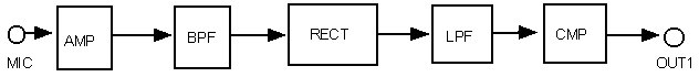
Figure 1 shows schematically the alert-sound detection process of existing systems.
The alert signal contaminated by background noise is picked up with a microphone, and then amplified, band-pass filtered, rectified, low-pass filtered, and compared to the threshold. Thus, basically only the loudness level of the sound is used to discriminate alert signal against background noise.
 |
However, human being utilizes other cues to detect alert signals. Among them, one or two specific main frequency spectra and time duration of the signal are the most important. In this study PLL was used to detect the specific frequency spectrum and PIC was used to determine the time window to the duration of the alert signal.
DESIGN
Figure 2 shows schematically the PLL circuit. The alert signal is picked up with a microphone, and band-pass filtered (BPF: 300-1,000Hz). The output of the BPF is compared to a reference voltage and a logic pulse signal (A) of which phase is +180 degree off the output of BPF is generated. The output of BPF is also fed to PLL and logic pulse signal (B) in-phase of its voltage-controlled oscillator (VCO) is obtained. When PLL locks to the incoming signal, the phase of VCO shifts between -90 to +90 degree from incoming signal, depending upon the phase difference between the signal frequency and free-running center frequency (Fo) of VCO. The phase difference is zero when the incoming signal frequency is equal to Fo. Thus, taking XOR of A and B, and then feed the resultant pulse trains to a low-pass filter (LPF) yields an analog signal, which represents the degree of tuning of the input signal to Fo.
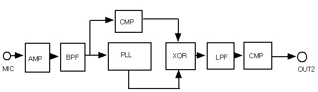 |
When the input signal is a true noise, PLL does not lock, and the relation between A and B is random. In this case, the output of LPF fluctuates around midpoint of the two logic levels. Thus, by pre-adjusting Fo and the threshold level of a succeeding comparator, the existence of main spectrum can be judged.
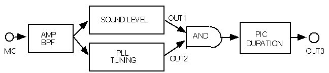
Figure 3 shows the block diagram of the total detection circuit. The output of the sound level circuit (OUT1) and PLL tuning signal (OUT2) are fed to logical AND. Thus, a signal that exceeds predetermined loudness level and has close main frequency spectrum to Fo is detected. PIC monitors the duration of the output of the AND circuit, and emits a logical output (OUT3) only when the duration of the output of the AND circuit falls a predetermined adjustable time window. In this way, signal duration gate is implemented in the circuit.
 |
EVALUATION
The benchmark models were used in two deaf families for one month to detect various alert signals contaminated by surrounding living noise. The power of signal detection was set to the level of existing systems, and the frequency of false alarm was noted. The results showed that the present system had much lower probability of false alarm, 10 to 15 % of existing systems. The only exception was baby cry. The reason was that baby cry does not have fixed main spectrum and duration, Thus the PLL scarcely locked the cry sound and time window did not work.
CONCLUSION
PLL and PIC circuits were newly introduced to the alert signal detection circuit in order to add frequency tuning and signal duration window. The benchmark test results were veru promising. This scheme is scheduled to be implemented in a commercial alert signaler in the near future.
REFERENCE
- The Western Institute for Deaf and Hard of Hearing, http://widhh.com
Shinji Miyazaki
Institute of Biomaterials and Bioengineering
Tokyo Medical and Dental Unversity
2-3-10, Kanda-Surugadai
Chiyoda, Tokyo, 101-00062, Japan
+81-3-5280-8088, +81-3-5280-8048(fax),
miyazaki.bmi@tmd.ac.jp