A Task Timer for Special Education
Abstract
A task timer facilitates teaching of students by graphically displaying the time period allotted for an activity. This paper describes a specialized task timer intended for use in special education classes with students who have severe cognitive, physical, or learning disabilities. These students need accommodation in understanding and responding to the allocation of fixed time periods for activities such as play, work, breaks, etc. This timer displays the set, elapsed and remaining portions of the selected period of time. The assessment of the timer requirements and the design of a three-part active display are detailed.
Background
Many students in special education and life skills classes experience difficulty with time management. Special education teachers in the Life Skills class at Westlake Ninth Grade Center in Austin, Texas, have observed shortcomings with their current time-management aids such as analog and digital clocks and timers. These teachers presented a request for a device that could help to bring time management into the conceptual grasp of these students.
Teachers observed that many students experienced difficulty with the concept of time because of cognitive, visual or learning disabilities. Research has shown that students with learning disabilities such as Attention Deficit/Hyperactivity Disorder (ADHD) have faster internal clocks, and that individual differences in perception of time are related to impulsivity and inattention (1). Students with ADHD may need different levels of stimulation to keep them focused (2). Examples of accommodations for deficits in organizational skills and time management are LCD watches, data bank watches, timers, counters and alarms (3).
Product Requirements
The population for whom the product was intended divided easily into two groups: students and teachers. It was determined that the teachers were the customers because they had expressed the need for the product initially and articulated the requirements during the development process. Valuable comments were provided by some of the students; however, in general it was concluded that the opinions of experienced professionals should be strongly weighted.
A conventional, mechanical kitchen timer was of limited usefulness in the special education class. A kitchen timer, while it presents an analog display of remaining time and of the one-hour time period, does not keep a record of the original set time Digital electronic timers were even less appropriate for this application in that a higher level of abstraction is required.
Design
Major design decisions included the motion of the display elements; whether to use a numerical scale; and the details of presenting the scale, the elapsed time, the remaining time, and the set time to the user.
Motion of Display Elements
It was debated at some length whether the user should observe the powered moving element, termed the “counter,” to rotate clockwise or counterclockwise. (The counter is the analog to the minute hand of a conventional clock or the pointer of a kitchen timer.) Clocks rotate clockwise, but kitchen timers decrement time while rotating in the counterclockwise direction. This question was bound up with the question of the fundamental purpose of the product: whether it was intended to time tasks; to teach the concept of time; or to help the students learn to read a clock. Counterclockwise rotation was chosen since the practical need to time tasks predominated and the device would be analogous to a conventional timer.
Numerical Scale
Since the division of time into seconds and minutes is a culturally imposed artificiality, it was discussed whether it might be more useful with some of the students to display time and its passage in a completely analog way, with no numerical scale in view and with the relevant time segments represented simply as colored areas changing in size. No method to determine whether this approach was actually useful could be found, since the students that might be expected to benefit from it were also those with whom communication about the issue was most difficult. Finally it was determined to provide a removable numerical scale, and let the timer itself be an experimental device to explore this question casually, directly in the classroom at the discretion of the teachers.
Display Details
Since it was desired to emphasize to the students the establishment and then the depletion of a particular segment of time, a method of indicating the original set time while simultaneously indicating the constantly-changing remaining time was needed. In effect, this meant that, in addition to set time, both remaining time and elapsed time should be displayed. This conclusion raised somewhat intricate issues whose solution formed much of the heart of the device.
Taking into consideration these requirements, it was concluded that the display viewed by the user must comprise three segments, somewhat analogous to the well-known pie chart. One segment indicates the initial set time; one the elapsed time and one the remaining time. Conceptually these are indicated in Figure 1 which shows three positions of the display.
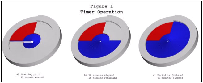 During
a single timing episode, the Set Time segment is established by the user
and then remains fixed. The remaining portion of the display is then divided
between the Elapsed Time segment and the Remaining Time segment, both of
which obviously change as time passes. In effect, the edge of the counter
sweeps through and converts "remaining time" into "elapsed
time" by converting it from grey to blue.
During
a single timing episode, the Set Time segment is established by the user
and then remains fixed. The remaining portion of the display is then divided
between the Elapsed Time segment and the Remaining Time segment, both of
which obviously change as time passes. In effect, the edge of the counter
sweeps through and converts "remaining time" into "elapsed
time" by converting it from grey to blue.
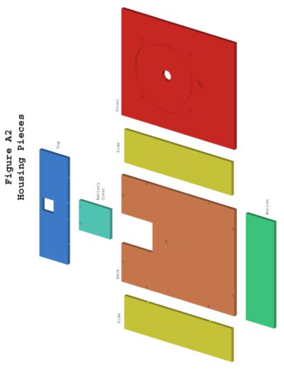
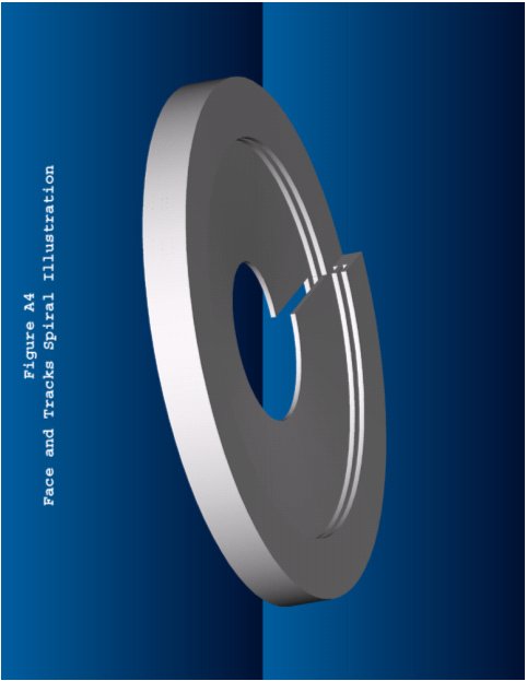
The grey fixed element, designated the "face," is an integral part of the timer structure and does not rotate. It can be exposed to view or hidden in any proportion, depending on the positions of the two moving elements. The exposed portion of the face represents the remaining time. The face is in the shape of a shallow spiral, analogous to a circular ramp in a parking garage, making one single complete circle. It is fabricated by making a radial slit in a circular disc with a large central hole to prevent twisting, then fixing the resulting cut ends to form a slot. The counter and set disc move into and out of view by sliding through this slot on spiral tracks.
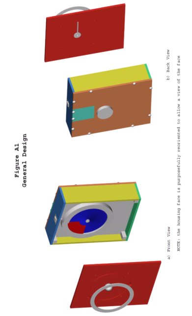
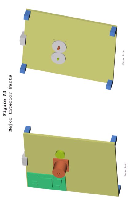
The red set disc and blue counter move in grooved, spiral tracks along the outside radius of the display. Both discs, similar to the face, consist of one single circular spiral. The spiral tracks in which they are constrained describe two complete rotations, one of which lies in front of the face (i.e., toward the user) and the other of which lies behind the face and out of the user's sight. This arrangement permits the placement of the discs totally out of view, as in the case of setting the timer for one full hour, or exposed in any proportion. The leading edge of the set disc represents the time period the timer is set for while the exposed portion of the counter represents the elapsed time. The user of the timer must adjust the position of the both discs before each timing event using a knob. The set disk knob is located on the front, while the counter knob is located in the back.
References
1) Gill, M. (2002). Neuropsychiatric Genetics Research Group. Retrieved 14 October 2002, from http://www.tcd.ie/psychiatry/neuropsychiatry/adhd6.htm
2) ADD In Schools (n.d.) Increasing Your Students’ Timed On-Task. Retrieved 14 October 2002, from http://www.addinschool.com/index.htm ADD in schools
3) Learning disabilities. Retrieved 29 November 2002, from http://www.jan.wvu.edu/media/LD.html
Acknowledgments
The authors extend their grateful appreciation to Dr. K. Wood and Dr. R. Crawford of the University Of Texas School Of Engineering, and to the teachers, staff and students of the Life Skills class at Westlake Ninth Grade Center in Austin, Texas.
Brian Oleson
1003 Justin Ln.
#2112
Austin, TX 78757
512-689-9339, boleson@austin.rr.com