Model Based Feedback Control for FES Cycling
ABSTRACT
The purpose of this work is to generate cycling motion for FES by using only knee extension and flexion muscles. Before the experiment, we investigated the possibility by simulation method. The musculoskeletal model used in this simulation was simplified as 5-rigid links and 2 muscles (knee extension and flexion). For the improvement of the present feedforward stimulation method, we included feedback path in the nervous system. Nervous system was represented by a rhythm generation system (RGS), peripheral system and a sensory feedback system. Nervous parameters were adjusted by a genetic algorithm (GA) that based on the natural selection theory. Cost function used in GA evaluated the energy consumption and the cycling speed of each generation. As a result, the optimization method, GA, generated the cycling motion by using only one knee extensor and one flexor. Closed loop stimulation method in this study is expected to be a new rehabilitative tool for SCI (Spinal cord injury) patient.
KEYWORDS
FES , cycling motion, feedback control, model-based, genetic algorithm
INTRODUCTION
To enable the paraplegic patient to stand up from the wheelchair and to keep standing for a period of time, the quadriceps muscles must be extensively trained through chronic electrical stimulation [4]. It is important not only to build up muscle force, but also to reduce fatigue. Besides, there are many benefits of electrical stimulation as to improve cardiovascular function and to increase muscle mass and bone density, etc.
 |
In this study, we focus on FES cycling that is a well-known method for FES training. Previous method used EMG of healthy subject in generation of the standard stimulation pattern. Because of the difference between healthy subject and patient, the pattern must be adjusted to each patient through burdensome trial and error modifications. And most clinically used FES system adopted a feedforward scheme based on the predetermined stimulation pattern. So, there was no way to solve problems like a disturbance or a change of physical condition.
We proposed a method using computer simulation model including the information of patient and feedback path. Neural system, corresponding to FES controller, generated stimulation pattern using the feedback information like joint angles and angular velocities. We focused on the lower extremities that play an important role in cycling. The human body was represented by a 5-rigid-link system where each joint angle was controlled by one neuron pair. Because there are limits of the number of stimulator channels and stimulatable muscles by surface electrode, we included only two muscles in the model. The cycling motion was optimized by applying the genetic algorithm to find the nervous parameters minimizing the performance index.
METHOD
1. Simulation model
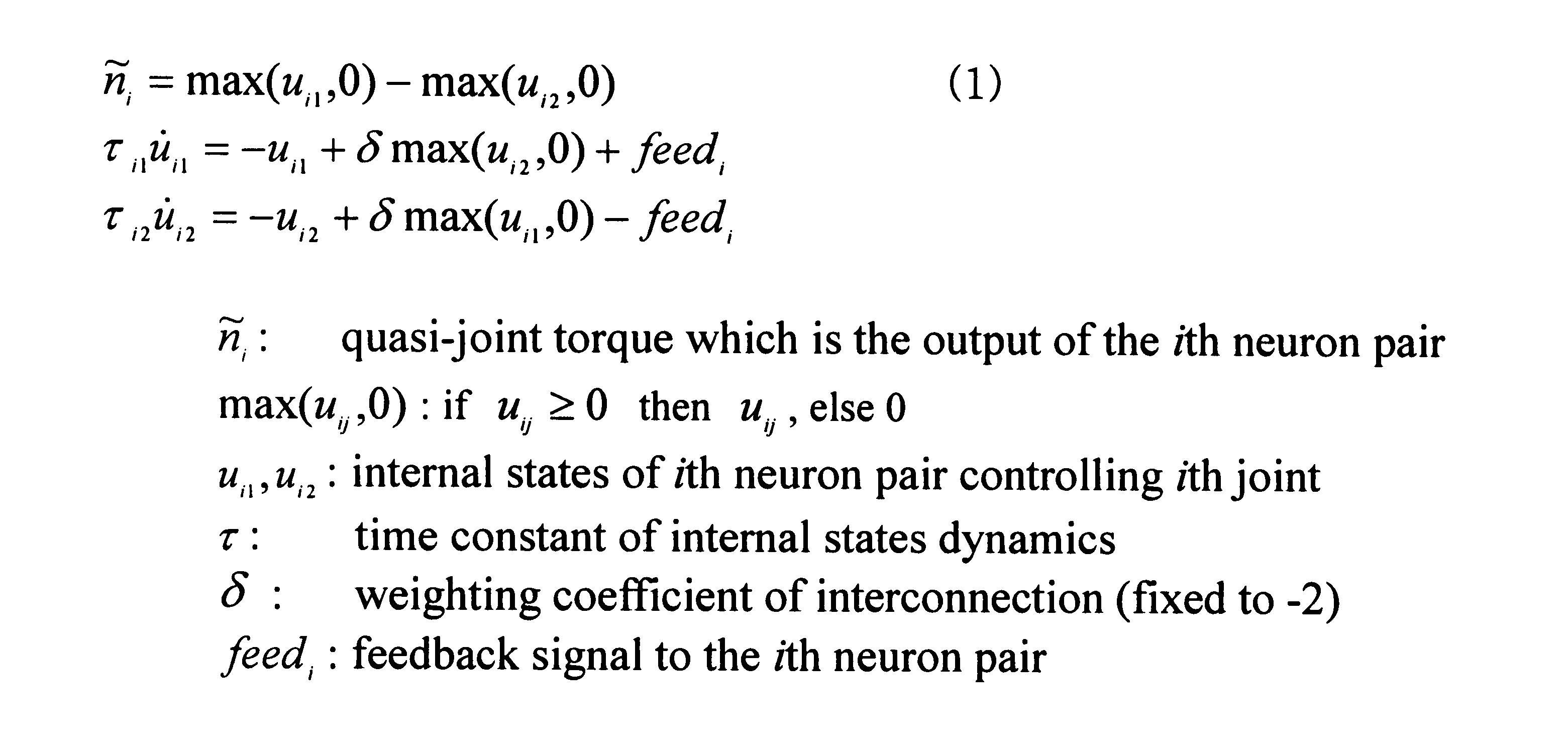 |
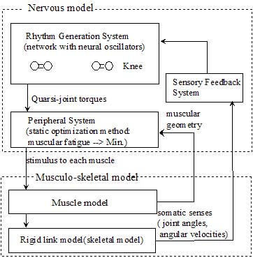
Fig. 1 shows the entire model structure. Nervous model, corresponding to FES controller, generated stimulation pattern using the feedback information as joint angles and angular velocities. The rhythm generation system generates a first-order delayed output the feedback signal. The output corresponds to the motion plan in the joint torque level and thus it is termed as the quasi-joint torque. The peripheral system converts the quasi-torque to electrical stimulation intensities. The musculoskeletal system generates a body motion by numerical integration of the equation of motion with the electrical stimulation as input. The information about the body motion, e.g. joint angles and ground reaction forces, are fed to the higher neuronal system through a feedback loop such as the somatic sensory system.
 |
1-1. Musculo-skeletal model
Because the number of muscles available in case of surface stimulation is often restricted, we included only knee extensor and flexor muscle in the simulation model. Hip joint was modeled not to generate active moment and ankle joint was modeled to be fixed by brace. We detailed the lower extremities rotating the crank, so the whole body was represented as a 5 rigid link of one HAT, two thighs, and two leg plus foot. The crank load of 20.7Nm was used in the simulation.
 |
1.2 Rhythm generation system
The system consists of two neuron pairs for both knees. The dynamics of the neuron pair is shown in equation (1) which is a modified form of the neural oscillator [2]. F eed (in equation 3) is the generated by sensory feedback system and will explain below.
 |
1.3 Peripheral system
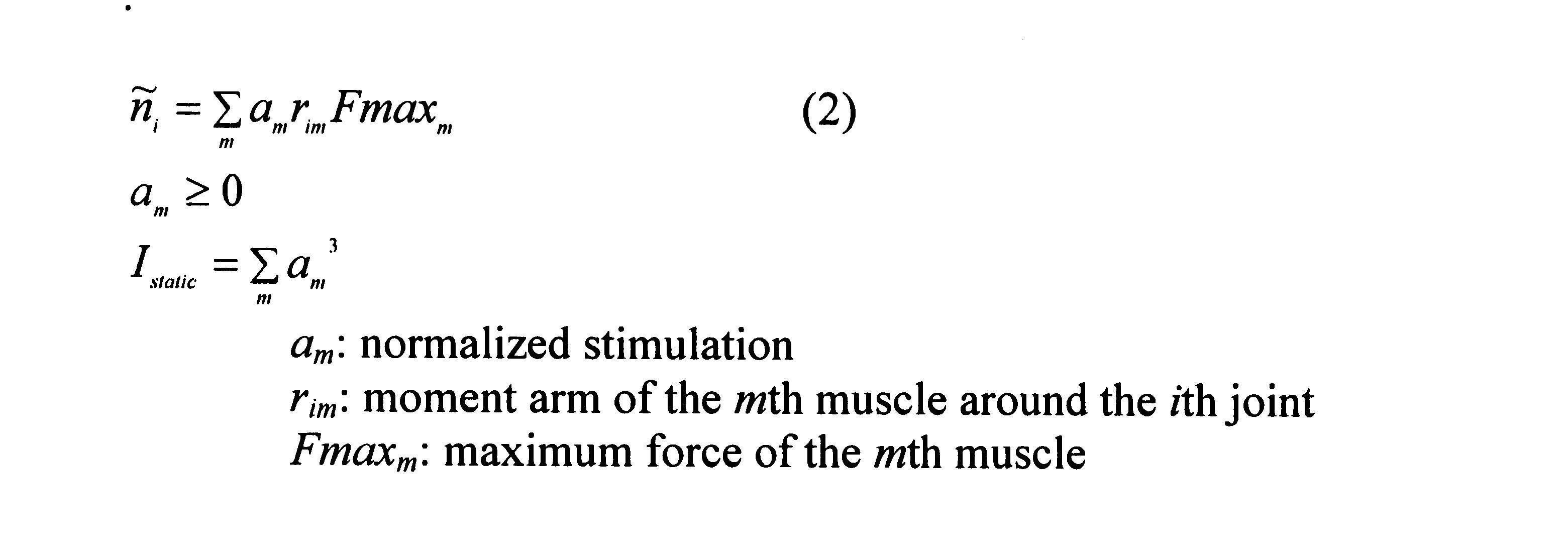
The peripheral system calculates the muscle stimulation from the output of the neural oscillator, i.e. the quasi-torque. There are infinite set of muscles producing the same torque. Therefore, we used a static optimization method (equation 2) to get the optimal muscle stimulation which can minimize the muscle fatigue.
1.4 Sensory feedback system
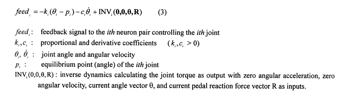
The sensory feedback system was designed based on the PD control theory (equation 3). The inverse dynamics was used to obtain the joint torque just to maintain the current posture so that the PD terms calculated can take care of the joint torque only to move the body segments away from the current posture.
 |
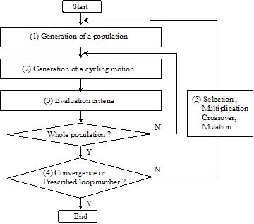
2. Search algorithm and performance index
Efficiency of the cycling motion is affected by the parameters in the nervous system. We used the genetic algorithm [3], which is a global search algorithms based on the natural selection theory to get the best parameters. We repeated the process (Fig.2) until the loop number reached 100000 or the performance index converged. Energy consumption and cycling speed were used in the performance index to assess the performance of the simulated motion with the present parameter values.
RESULT AND DISCUSSION
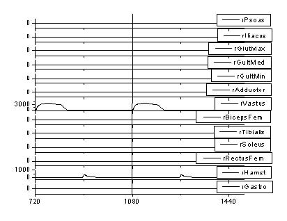 |
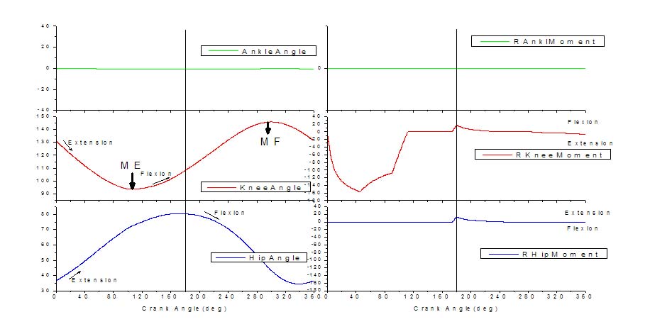
The computer simulation result in Fig. 3 and Fig. 4 shows joint angles and moments and muscle activation patterns. We used the hamstring which is a biarticular muscle, as a knee extensor. So hip extension moments were generated by this muscle. Our result shows that cycling motion can be generated by only using knee extensors and flexors.
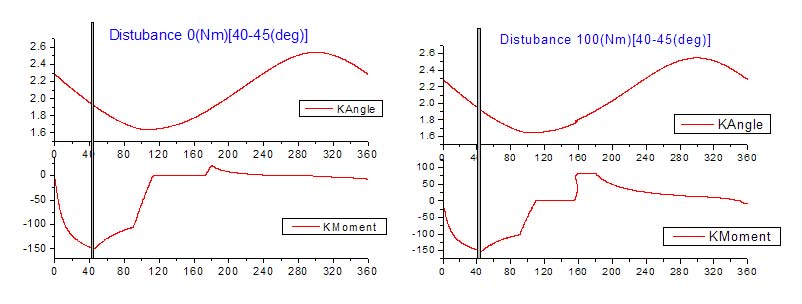
To examine the robustness of the suggested feedback method, we applied disturbances during motion. The disturbance was applied when the crank passed between 40 ° and 45 ° . Tow kinds of disturbances, lower load (0Nm) and higher load (100Nm) than the normal crank load (20.7 Nm) were applied. From these simulation results of Fig 5, we can see cycling motions were generated successfully in spite of the disturbances.
 |
In case of clinical application, the necessary feedback signals are joint angles, angular velocities, and crank angle. The crank angle can be easily measured and the joint angles and angular velocities can be calculated from the crank angle.
REFERENCES
- Alojz Tadej Bajd 1995
- Kazunori Hase, Motoshi Kaya, Nobutoshi Yamazaki, Brian J. Andrews, Amy B. Zavatsky, Suzanne E. Halliday, Biomechanics of rowing (1. a model analysis of musculo skeletal loads in rowing for fitness , JSME Internatinal Journal Vol. 45, No. 4, pp. 1073-1081, 2002
- Goldberg, D. E., Genetic Algorithms in Search, Optimization and Machine Learning, Addison Wesley, 1989.
- A. J. Mulder, H. J. Hermens, F. Janssen, G. Zilvold, A low-cost FES exercise bicycle for training paraplegics at home, Journal of Medical Engineering & Technology, Vol 13, No. 1/2, pp 90-92, 1989.
ACKNOWLEDGMENT
This work was funded by the Basic Research Program of the Korean Science & Engineering Foundation grant #R01-2002-000-00192-0
Author contact Information
Gwangmoon EOM,
Assistance professor, Konkuk University,
Danwol-dong, Chungju,
Chungbuk, Korea, 380-701,
Phone 82-43-852-9890,
EMAIL: gmeom@kku.ac.kr