Rigid link-segment models as predictors of semi-reclined leg cycling kinematics
ABSTRACT
The purpose of this study was to compare the accuracies of four-bar and five-bar link-segment models to predict semi-reclined leg cycling kinematics in SCI and AB subjects. Joint kinematics data of the hip, knee, and ankle were evaluated and compared between the experimental and two different link-segment model types (four-bar and five-bar link) using data collected form a spinal cord injured (SCI) and an able-bodied (AB) individuals during semi-reclined steady cadence stationary leg pedaling. Experimental data were obtained using motion capture. SCI subject pedaled with electrical stimulation to upper leg muscle groups and AB individual pedaled without electrical stimulation. The accuracies of the models were measured using root-mean-square errors (RMSE). It was concluded that both models tend to oversimplify lower limb kinematics. However, the five-bar model appeared to be a more appropriate tool in predicting the kinematics of leg cycling for both subjects.
KEYWORDS
Kinematic Modeling, Leg Cycle Ergometry
BACKGROUND
Predicting the movement patterns of leg pedaling through kinematic modeling is a valuable tool for improving the design and development of leg cycle ergometry systems. Kinematic analyses may be used in defining movements of the leg segments and joints (hip, knee, and ankle) in terms of position, velocity and acceleration to predict correct movement patterns based on bike geometry configurations and rider anthropometries. The development of kinematic link-segment models could also be utilized to develop appropriate controls that would deliver proper timing and sequencing of muscle activation during electrically stimulated (ES)-induced leg cycling for the most efficient ride for people with SCI.
Although kinematic models have been developed to emulate able-bodied (AB) individuals during upright leg cycling [1, 2], details regarding kinematic models of AB and SCI individuals in a semi-reclined position are limited. Previous studies involving kinematic modeling of ES-induced leg cycle ergometry have used rigid planar four-bar link segment models to characterize joint kinematics [3]. These approaches were considered appropriate because the rider-bike geometries induced by the stimulated muscles of the upper leg do not affect ankle motion and the fact that ankle motion is restricted by the bike design. Recently, we found that muscles surrounding the ankle (gastrocnemius and tibialis anterior muscles) were electrically active during semi-reclined leg cycle ergometry which questions the ability of a four-bar link-segment model to characterize fully the rider-bike geometry [4]. In order to allow for modeling of the ankle joint, an additional degree-of-freedom (DOF) is required over the four-bar link segment model. Early studies described the kinematics of the leg during upright pedaling by modeling it as a five-bar link [1, 5]. The five-bar planar link segment model considers motion at the ankle possible.
The purpose of this study was to compare the accuracies of four-bar and five-bar link segment models to predict semi-reclined leg cycling kinematics in SCI and AB subjects. Since the lower leg muscles are not activated during ES-induced leg cycling, the kinematics of an AB individual was compared to a SCI individual using the two models.
METHOD
Experimental Data Collection
Kinematic data were collected from a healthy SCI individual who was a regular user of ES-induced semi-reclined leg cycling (have used the system for least 3 months) and a healthy AB individual. Both subjects signed an informed consent form approved by the university's IRB. Subjects were comparable on anthropometric characteristics and were tested on the standard ERGYS ® bike (Therapeutic Tech. Inc., Fairborn, OH USA) during steady-state cadence (50RPM) and resistance level of 6.25Watts (SCI) and 60Watts (AB). AB subject did not receive ES. A video-based motion capture system (Peak Performance Technologies ® Inc., Denver CO , USA ) was used to evaluate sagittal motion of the pedal crank, hip, knee, and ankle. Thirty seconds of motion capture data were collected two minutes after the subjects started pedaling. Angular velocity and acceleration were computed by taking first and second derivatives of the angular position data, respectively.
Kinematic Modeling
 |
Leg motions were modeled in one plane as a closed-loop. The modeled links resembled leg segments connected together by joint articulators. All joint articulators were modeled as revolute joints. Since the link segments of the two legs are considered coupled at the crank by 180 degrees of rotation. The output of the kinematic models provided information on crank, pedal and joint positions, velocities, and accelerations. The lengths of the upper leg, lower leg, and pedal to ankle distances were used in the calculations of angular positions, velocities, and accelerations. Both models assumed fixed hip joint and crank axis. The one constraint that specified the link-segment configuration was the measured crank angle. The four-bar model considered the foot-pedal configuration to be fixed. However, the five-bar model considered the foot-pedal configuration as not fixed and modeled the ankle as a revolute joint to account for dorsiflexion and plantar flexion. The relative foot-pedal angle was approximated using a sinusoid function to best fit the experimental data [6].
RESULTS
 |
The accuracies of the model were evaluated for each joint's kinematics of both subjects. The last ten crank rotations (pedal cycles) of steady-state pedaling were analyzed. All representative cycles met a criterion of ±2 RPM of the targeted cadence of 50RPM. Ensemble averages along with standard deviations were computed for hip, knee, and ankle joint angular positions, velocities, and accelerations of the experimental data relative to crank angle. Model accuracy was assessed using root-mean-square error (RMSE) percentages.
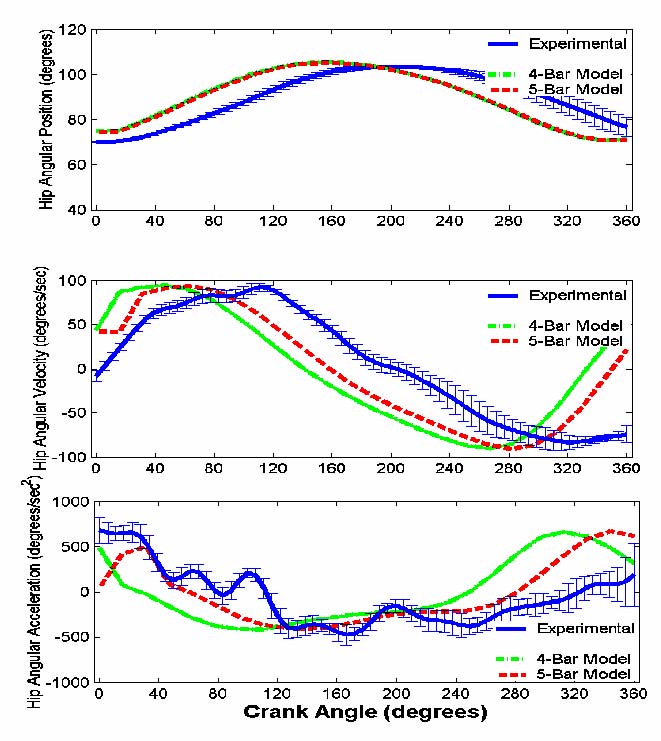
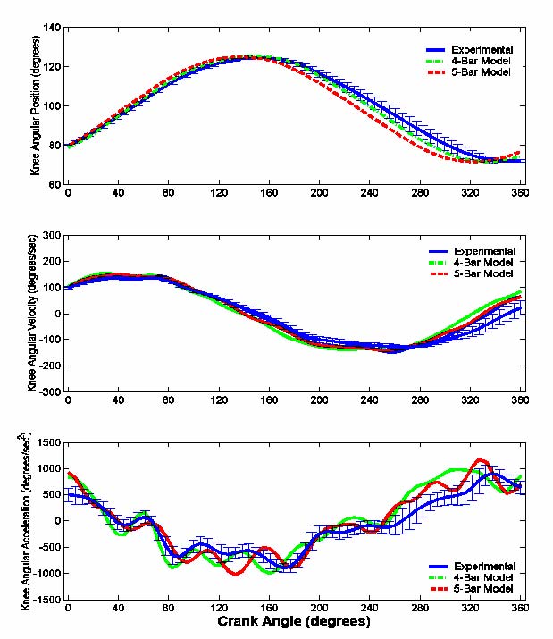
Both the four-bar and five-bar models nicely represent the hip and knee joint kinematics for both subjects with RMSE percentages within 20% of experimental data (Figures 1 and 2
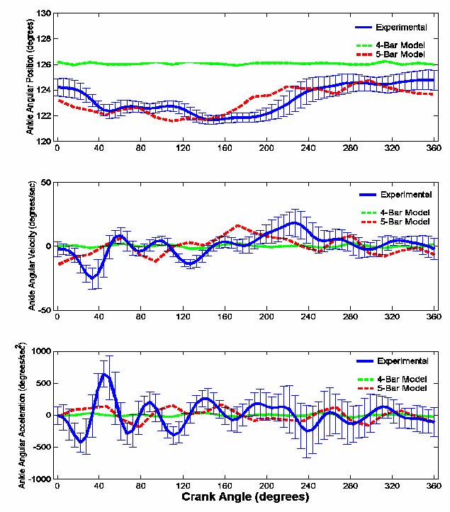
However, the kinematics were different between the four-bar model (ankle considered fixed with no motion) and the experimental data for ankle kinematics (Figure 3).
 |
DISCUSSION
In comparing the two models, the five-bar link segment model data did exhibit lower RMSE values for both subjects, but more specifically with the AB subject. The major distinction between the two models was in the differences in ankle kinematics. The five-bar model was within 20% RMSE percent of the experimental data for both AB and SCI subjects. However, the four-bar model had a greater RMSE for the AB and SCI subject. Although AB subject performed semi-reclined leg cycling on the same system as the SCI subject, the sagittal ankle kinematic results from AB subject appear to have greater range of movements. This is not surprising since AB individuals have greater numbers of muscles to assist during pedaling. The restricted boot-pedal limited ankle movements for SCI, but less in AB subject pedaling against resistance. For the AB subject, the ankle position greatly influences force transmission between the foot and pedal [7], which is somewhat restricted in the current boot-pedal design. Future kinematic models of semi-reclined leg cycling geometry may consider the shank and foot segments as not rigidly fixed. Permitting sagittal plane motion about the ankle joint may be an acceptable alternative to the pre-existing system design.
REFERENCES
- Hull, M.L. and M. Jorge, A method for biomechanical analysis of bicycle pedalling. J Biomech, 1985. 18 (9): p. 631-44.
- Neptune, R.R. and W. Herzog, Adaptation of muscle coordination to altered task mechanics during steady-state cycling. J Biomech, 2000. 33 (2): p. 165-72.
- Schutte, L., M. Rodgers, and F. Zajac, Improving the efficacy of electrical stimulation-induced leg cycle ergometry: An analysis based on a dynamic musculoskeletal model. IEEE Transaction on Rehabilitation Engineering, 1993. 1 : p. 109-125.
- Trumbower, R. and P. Faghri, A time-sequence analysis of EMG measurements during semi-reclined leg cycling. Engineering in Medicine and Biology, 2003. accepted for publication .
- 5. Neptune, R. and M. Hull, Evaluation of performance criteria for simulation of submaximal stead-state cycling using a forward dynamic model. Journal of Biomechanical Engineering, 1998. 120 (3): p. 334-341.
- Redfield, R. and M.L. Hull, On the relation between joint moments and pedaling rates at constant power in bicycling. J Biomech, 1986. 19 (4): p. 317-29.
- Neptune, R. and M. Hull, A theoretical analysis of preferred pedaling rate selection in endurance cycling. J Biomech, 1999. 32 (4): p. 409-415.
Author Contact Information:
Randy D. Trumbower, MS, PT, PhD Candidate,
University of Connecticut,
256 Mansfield Road,
Storrs, CT 06266,
Office Phone (860) 486-1773
EMAIL: randy.trumbower@uconn.edu