Development of Head-Operated, Isometric Controls for Powered Mobility
ABSTRACT
Position-sensing joysticks and switch arrays have been the traditional means of interface for chin control users of electric powered wheelchairs. In this study, a force-sensing chin-operated joystick has been developed as an alternative to these devices. The important difference between a position-sensing joystick and a force-sensing joystick is that the latter requires no range of motion, which may allow for easier, more comfortable chin control. The mechanical design of the chin controlled force-sensing joystick includes a base, force-sensing beam, covering case, and mounting bracket. The electrical design is comprised of two strain gage bridges, two instrumentation amplifiers, Tattletale control board, and a digital to analog converter. Software has been designed so that it determines the output characteristics. The software flexibility allows for customization of performance characteristics such as asymmetric or symmetric force, adjustable force sensitivities, and filter tuning.
KEYWORDS
Power Wheelchair, Joystick, Force-sensing Joystick, Chin-operated Joystick
BACKGROUND
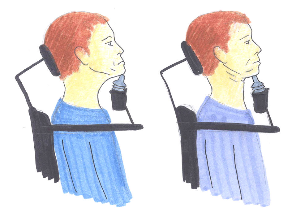
It is has been estimated that the prevalence of SCI in the United States is between 183,000 and 230,000 persons. Fuhr et. al. surveyed 65 practicing clinicians in a variety of health care settings about types of interfaces used by their clients (1). The clinicians reported that 9% of patients use chin or head control. Head control interface devices for EPWs and other assistive technologies fall into three categories: switch arrays; joysticks; and motion detection systems. An array of three switches is usually positioned on the headrest and activated by bumping the switches with the back of the head. The disadvantage of switch arrays is that they do not offer proportional control and only offer left, right, forward, and backward directional options. Chin-operated joysticks are typically position-sensing joysticks (PSJ), which requires some range of motion. Position-sensing joysticks are also problematic because they are challenging to stabilize. They also require flexion, extension, and rotation of the jaw and neck, which may be difficult for some users. The motions associated with PSJ operation are illustrated in figure 1. Prolonged operation of PSJs has been known to cause fatigue and pain for some users.
 |
|---|
An alternative to the position-sensing joystick is the force-sensing joystick (FSJ). Force-sensing joysticks for hand control have been developed by Riley and Rosen (2), and Cooper et al. (3). Unlike the motion detection systems and PSJs, a FSJ requires no range of motion because the stick is stationary and requires only a small force to activate. The FSJ differs from the switch array because it offers proportional control and is not limited to four directional choices.
Hand operated FSJ for EPWs in research have used micro-controllers and software algorithms to compensate for tremor, vibration, and other undesired movements. Pilots and surgeons have also benefited from control systems that reject tremor and vibration. Riley and Rosen compared hand controlled FSJ and PSJ for EPW use concluded that no one type of joystick or software filter could universally benefit all subjects; however, performance could be improved by providing each subject with a custom fit.
MECHANICAL DESIGN
 |
|---|
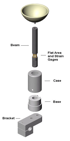
The mechanical design included a base, covering case, mounting bracket, and beam as shown in figure 2. The most important component of the mechanical assembly was the beam, which was responsible for receiving force input from the user. The dimensions and material of beam were carefully chosen in order fulfill the design criteria. To meet these specifications, a cylindrical beam of 9.525 mm diameter, 92.075 mm long, hardened tool steel was used. Near one end is a flattened side to receive a setscrew. Above the flattened setscrew edge are four faces that were ground flat for the mounting of the strain gages.
The base, covering case, and mounting bracket are made of aluminum and were designed to compliment the beam. The general shape of the base and the covering case is a cylinder because it occupies less volume than a box of comparable dimensions and it can be readily turned from round stock. The function of the base was to hold the beam up right and prevent it from rotating. The covering case protected the strain gages and wires near the base on the beam. It was received by the base and allows the beam to pass through without touching. It is important that the covering case not touch the beam, so force could be transmitted along its length uninterrupted. The mounting bracket was the link between the base and joystick support apparatus. One end of the mounting bracket screws to the base and the other is clamped to the round arm of the support apparatus.
ELECTRICAL DESIGN
The electrical hardware of the joystick consists of the strain gages, amplifiers, a commercial control board, and a digital to analog converter. The strain gages are mounted to the beam and form two separated bridges. One of the bridges controls speed, forward-backward axis, and the other direction, left-right axis. The signals from the strain gage bridges are amplified and filtered by the instrumentation amplifiers before they are sent to the Tattletale TT8 control board (Onset Computer Corp, Bourne, MA ). The Tattletale control board was chosen because it fulfilled important design criteria. It contains an analog to digital (AD) converter to sample the amplified signals, a micro-controller, and has programmable memory that is used to store a signal-processing program. After the data logger processes the signal, the data is sent to the digital to analog converter (DAC). The processed analog signal is then ready to control the power wheelchair.
The strain gages, EA-06-125PC-350, were used to form two full electric bridges. A pair of EA-06-125PC-350 strain gages was attached using two-part glue to each of the four flat sections of the beam. The strain gages on opposite sides of the shaft form each bridge. This geometry results in one bridge for controlling forward and reverse motion and the other for controlling left and right turns.
An INA118 instrumentation amplifier was chosen to amplify the strain gage signals. This amplifier is chosen because of its high input impedance, a maximum offset voltage of 50µv, and a maximum bypass input current of 5nA. The gain is adjustable and has a high minimum CMR of 110db. Another important feature of this portion of the circuit is the low pass filter. It is an R, C filter that has a cutoff frequency of 10 Hz.
SOFTWARE DESIGN
The purpose of the data processing software is to generate the desired output curve over the range of inputs. The program accomplishes three major tasks: it samples data, decides what the output should be based on the input data, and relays this information to the DAC. First the initial voltage of the neutral position of the joystick is sampled 25 times and averaged. The program then enters the main operating loop, which periodically samples the signal from the strain gages and filters the data by averaging 25 samples. These samples are compared to the neutral position sample by taking the difference of the two. The difference is tested using logic to determine what range the input is included. An output curve is created for each range base on the desired performance characteristics of wheelchair. The output curve for each range can be either a constant value or a function of the input.
RESULTS AND DISCUSSION
The joystick's most important design characteristic was its programmability. A key feature of the output curve was directional symmetry and asymmetry. On the left and right axis, output was symmetrical, which is important for predictable driving. It is significant to note that output could be made asymmetrical on the left-right axis to accommodate users that have limited strength on one side. The asymmetry of the forward-reverse axis was designed for easier forward driving, while at the same time limiting backward driving for safety reasons.
Another important aspect of driving was direction orientation of the joystick. Driving forward was initiated by pressing backward on the joystick. During a collision while driving forward, the users body will continue forward due to inertia. A force in the forward direction on the joystick will cause the wheelchair to travel backward, so in the case of the obstacle the natural forward motion of the user will stop the chair or cause it to move away from the obstacle. This could reduce the severity of a collision, which reduces the risk of injury to the user. Additionally, the headrest limits the users forward driving by stopping the head from moving backward during forward acceleration.
The drive test showed qualitatively that the joystick could be used to navigate an EPW through a variety of obstacles. The obstacles include doorways, ramps, and confined spaces. The wheelchair could hold a straight line without frequent adjustment, and it could make sharp turns. The maximum forward speed was measured at 1.1 m/s, while the maximum backward speed was 0.12 m/s. Backward driving was initiated by pushing forward on the joystick and was considerably slower as an additional safety precaution.
REFERENCES
- Fuhr L, Langbein WE, Skaar, SB: Adequacy of power wheelchair control interfaces for persons with severe disabilities: A clinical survey. J Rehabil Res Dev 2000;37(3):353-60.
- Jones DK, Cooper RA: Electro-mechanical devices for control of powered wheelchairs. Saudi J Disabil Rehabil, 1998;4(3):200-206.
- Riley PO, Rosen MJ: Evaluating manual control devices for those with tremor disability. J Rehabil Res Dev 1987;24(2):99-110.
- Cooper RA, Widman LM, Jones DK, et al: Force Sensing Control for Electric Powered Wheelchairs. IEEE Trans Contr Syst Technol 2000;8:12-117.
Author Contact Information:
Songfeng Guo,
Human Engineering Research Laboratories,
7180 Highland Drive
151R-1,
Pittsburgh, PA 15206,
Office Phone (412) 365-4852
Email: sguo@pitt.edu