Isometric Joystick Tuning Interface and Assessment
ABSTRACT
The purpose of the study was (1) to develop a clinical-based joystick tuning interface for customizing joystick parameters, and (2) to develop a virtual simulation environment to access the user's performance with a customized joystick versus a standard joystick. The virtual simulation environment can also be utilized for wheelchair training purpose. The joystick tuning interface enables clinicians to choose different templates and find personalized dead zone and bias axis for each individual subject, especially people with traumatic brain injury (TBI) or multiple sclerosis (MS). The virtual simulation environment includes a 2D driving course and a simplified wheelchair model, where the performance driving with a standard joystick and a customized joystick can be compared in terms of the number of collisions and trajectory errors between the desired course and actual course.
KEYWORDS
Isometric joystick, tuning interface, virtual reality, simulation.
INTRODUCTION
Conventional power mobility training and assessment is usually expensive and sometimes unsafe. Building a virtual reality based simulation system could resolve the problem of cost and safety [1]. The application of virtual simulation permits evaluation of the user's ability to drive, and thus to choose the wheelchair and input device more appropriately. A large variety of electric wheelchairs are available on the market: wheelchairs for indoor and outdoor use, wheelchairs with front-wheel, middle-wheel, and rear-wheel drive. They all have their specific advantages and disadvantages for different users, and in different environments. Simulation can therefore give a first impression as to which kind of wheelchair will be suitable for the user. A very important aspect in wheelchair driving is the input device, usually a joystick operated via hand, head, chin or foot. Current joysticks use a limited set of machanical templates that are difficult to change or fit to individual users. The optimization of the joystick parameters based upon each individual user provide a means of allowing people who are unable to independently drive a powered wheelchair to do so, and enhancing efficiency and safety as well. The most suitable interface for an individual user can objectively be assessed by means of simulation [2]. In this study, we developed a virtual simulation environment to assess the user's performance with a customized joystick whose parameters are properly chosen and calcuated through a joystick tuning interface. This opens the possibility of defining a tailor made joystick, which is particularly beneficial to users with tremors, e.g. people with traumatic brain injury (TBI) or multiple sclerosis (MS).
METHODS
A force-sensing joystick was developed in our laboratories, which can produce a voltage output proportional to the force exerted on the stick by users. Based on this kind of joystick, we create a clinical-based joystick tuning interface, including selection of templates, calculation of the dead zone, and bias axis adjustment.
Templates are typically stamped or machined pieces of metal placed over the joystick housing to restrict the motion of the stick. Essentially, the stick hits the wall of the template and is restricted from moving further. Templates are used to control bias, to decrease the throw of the stick, and to reduce the degrees of freedom of stick movement. We have implemented four software templates (i.e. circle, ellipse, asteroid, and diamond) in the joystick-tuning interface. The template algorithm performs the point-in-template check and calculates the intersection points, so that the intended direction from the user can be maintained but the magnitude (i.e. speed and direction) will be readjusted according to the shape of the selected template. The size and orientation of these templates can be adjusted through the interface by clinicians to accommodate different cases.
The dead zone of a joystick refers to the minimum range of x and y forces that need to be exceeded in order to produce motion of the wheelchair. Wheelchair users with different diagnosis may have different patterns of tremor resulting in quite different dead zones. The tuning interface enables clinicians to collect force data in x and y directions when a user rest his/her hand comfortable on the stick for some time, and then computes the dead zone. The interface provides three options for the shape of a dead zone, i.e. a circle, a square or an ellipse. The elliptical enclosure was implemented in an incremental way so that a small enclosure could be guaranteed.
People with upper extremity impairments often have better control in a direction other than the orientation of the joystick axis. The joystick-tuning interface enables clinicians to find the bias axes for each subject beforehand and automatically transform the user's input to align with the bias axes. The bias axes were calculated using the least square fitting method where the sum of perpendicular offsets was minimized. The bias axis could be orthogonal or non-orthogonal, and a general transformation matrix was applied under the two circumstances to calculate the new speed and direction signals under the bias axes.
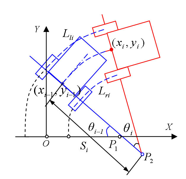
The virtual simulation system is consisted of a desktop monitor and a PC-based 2-D graphic system. This configuration has a small field of view and non-immersive, but it is well suited to evaluate the ability of wheelchair driving by providing a very clear view of the tracks ahead and wheelchair trajectories behind. The wheelchair is simply modeled with two rear driving wheels. Based on its kinematics, the new position of the wheelchair can be calculated as follows.
Define Lliand Lri as the distances traveled at sample time i by the left and right wheels respectively. In each step, Lliand Lri are calculated by reading the encoders on both wheels or pre-calibrated data. B is defined as the track width of the wheelchair.
 |
|---|
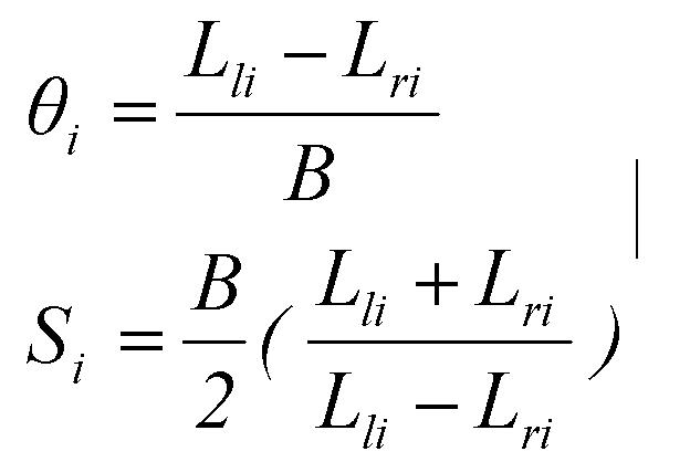
According to Figure 1, the change in direction θiand the instantaneous radius of rotation Si can be obtained by Eq. (1).
 |
|---|
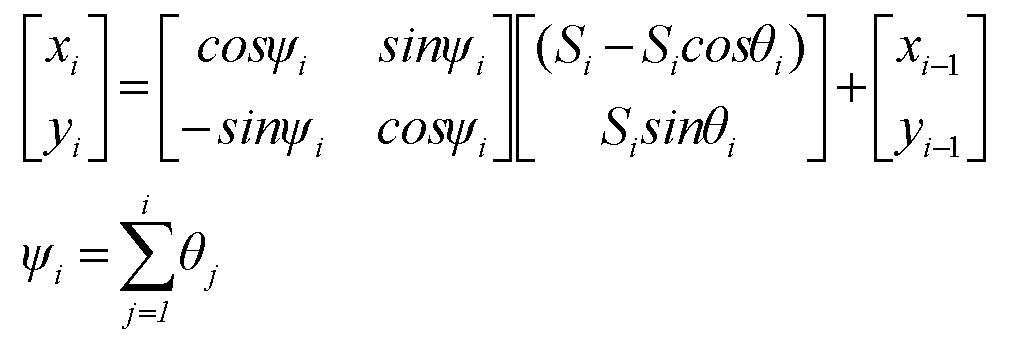
The new wheelchair pose (Xi,Yi,ψi) w.r.t. the world coordinate XOY can be obtained by Eq. (2).
 |
|---|
Currently, most wheelchairs have no encoder reading feedback, and we use the data calibrated for each specific wheelchair to provide the simulation software with feedback information.
RESULTS
 |
|---|
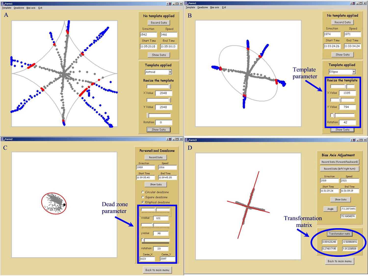
Figure 2 (a) and (b) showed the astroid and ellipse templates, wherethe size and orientation of each template can be adjusted. Points outside a template were identified in blue and intersection points were shown in red. Figure 2 (c) showed an elliptical dead zone, which can be customized case by case by finding a small enclosure surrounding all the points. Figure 2 (d) showed the new bias axis and the transformation matrix between the new frame and the old one. The transformation matrix is used to align the wheelchair with the bias axes.
 |
|---|
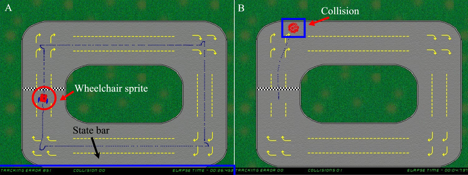
Figure 3 displayed the virtual simulation environments, where users are required to drive along the track and try to stay in the middle of the yellow dotted lines. The actual trajectory was plotted and the accumulated error between the actual trajectory and the desired one was displayed at the bottom of the screen. Collisions with the track can be detected.
DISCUSSION
Future work may involve in adding encoder feedback and wheelchair dynamics to accurately simulate wheelchair behaviors. The simulation environment will be further improved to include either static or dynamic obstacles so that the ability to stop before hitting an object or to reach a known position can be acquired through simulation. Although simulation offers a range of new possibilities, it is wise to mention that learning to navigate in a virtual environment is still far from equivalent to experience in the real world. Therefore, virtual environment simulation is advocated as a useful preparation for eventual real-life exploration within the real physical environment.
REFERENCES
- A. Harrison, G. Derwent, A. Enticknap, F. D. Rose, and E. A. Attree, Application of virtual reality technology to the assessment and training of powered wheelchair users, International Conference on Disability, Virtual Reality and Associated Technology , pp.15-22, 2000.
- M. Majdolashrafi, M. N. Ahmadabadi, and A. Ghazavi, A desktop virtual environment to train motorized wheelchair driving, IEEE International Conference on Systems, Man and Cybernetics, 2002 .
ACKNOWLEGEMENTS
The work is supported in part by the National Institute on Disability & Rehabilitation Research, and the Rehabilitation Engineering Research Center (#H133E990001) and in part by the VA Rehabilitation Research and Development Service, Veterans Health Administration, U.S. Department of Veterans Affairs (F2181C).
Author Contact Information
Dan Ding,
Human Engineering Research Laboratories,
VA Pittsburgh Healthcare
System
151R-1, 7180 Highland Drive,
Pittsburgh, PA 15206.
412-365-4850,
dad5@pitt.edu