Designing an Improved Variable Compliance Joystick for Driving Electric Powered Wheelchairs
Abstract
Commercial electric powered wheelchairs (EPW) are equipped with movement-sensing joysticks. While effective for many consumers, individuals with tremor may find it difficult to safely command their chairs with this control. The design of alternative joysticks to control electric powered wheelchairs has been previously investigated by [1-3] . Earlier investigators have reported some success controlling tremor with computational or mechanical filtering. This paper reviews theses early investigations and presents the design drivers for a force-sensing joystick that mechanically filters tremor.
Keywords
Intention tremor, force-sensing joystick, mechanical vibration isolation
Background
In 2000, Fehr, Lanbein and Skaar [4] describe the results of a clinical survey of 65 practicing clinicians in a variety of rehabilitation services from 29 states. The clinicians reported that between 10 and 40% of their clients who desired powered mobility devices could not be fitted with electric powered wheelchairs (EPW) because sensory impairments, poor motor function or cognitive deficits made it impossible for them to safely drive a power wheelchair with any of the existing commercial controls. Individuals with movement disorders are often the most underserved population. For example, multiple sclerosis (MS) movement disorders are unusually difficult to manage because cerebellar/Rubral tremors that occur with MS are virtually unresponsive to medication. The objective of this supported research is to develop a variable compliance joystick for consumers who might otherwise be unable to obtain powered mobility.
Several investigators have examined methods for reducing the effects of operator tremor. Riley and Rosen [5] chose to use computer software to mitigate the effects of tremor. They concluded that individuals benefited from tremor mitigation and that customized configurations are necessary. However, mechanically damping tremor at the source may be better than using computer software. In the late 70s through the early 90s, Beringhause et al [6] investigated a mechanically damped, position-sensing joystick using viscous fluid. More recently, Spaeth et al [7] have examined a "pure" force-sensing joystick as well as a force-sensing joystick with gain modification. While results have been favorable, the potential benefit of combining mechanical damping and software filtering with variable gain has not been investigated. The objective of this research is to design a joystick that mechanically isolates tremor and can be easily customized for individual consumers.
Deuschl et al [8] report clinical classification of tremor in terms of frequency f as low ( f <4 Hz), medium (4< f <7 Hz), and high ( f >7 Hz). For essential tremor, the frequency range can be between 4 Hz and 17 Hz, while the most common frequencies are 4-8 Hz and 12-17 Hz. Research has also shown that tremor is time dependent for the individual [8, 9]. Elble reported that the range for early tremor is 8-12 Hz, and the range for advanced tremor is 4-8 Hz. Similarly, Deuschl et al show that the frequency may decrease between 2 and 3 Hz over a 4-8 year period.
The mass involved in essential tremor is variable among individuals. The 5 th percentile female has a hand/forearm mass of 0.47 kg, while the 95 th percentile male has a hand/forearm mass of 2.16 kg [10].
Design approach
The joystick can be modeled using the equations for mass-spring-damper systems as follows
where x , x-dot , and x-double-dot are the position of the vibration isolator and its time derivatives, respectively; the damping ratio z is given by c /(2 m w n ); c is the damping coefficient; m is the sum of the masses of the joystick handle and the user's hand and forearm; the natural frequency of the system w n is given by
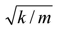 |
; k is the spring constant; f 0 is the effective acceleration of the tremor given by F 0 / m , where F 0 is the tremor force; w f is the angular frequency of the tremor given by 2 p f ; and t is the time. Figure 1 (a) depicts a simple model of the system.
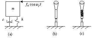 |
An oscillating force is applied horizontally to the top of a vertical joystick handle. A spring-damper system separates the handle from the base, which houses the strain gauges, as shown in Figure 1 (c).
When choosing an appropriate spring constant and damping parameter for a force-sensing joystick, it is important to look at the ratio between the applied force F 0 and the transmitted force on the joystick F T , which can be given by [11]
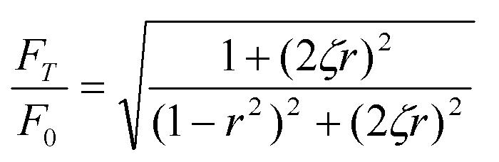 |
where the frequency ratio r is w f / w n . Figure 2 depicts this ratio in terms of the hand's vibrating frequency.
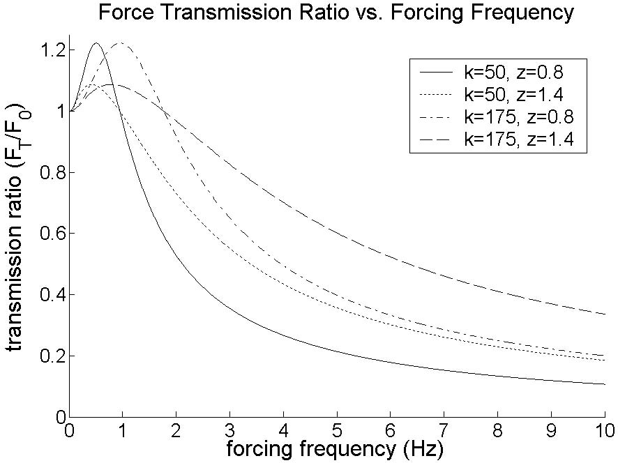 |
The curves are representative for the 50 th percentile male (2.82 lbm), spring constants k 1 = 50 and k 2 = 175 lbs/in, and damping ratios z 1 = 0.8 and z 2 = 1.4. Here, it is important to mitigate vibrations that result from tremor ( f > ~5 Hz) but to maintain intentional frequencies for wheelchair guidance ( f < ~2 Hz). Conversely, movement within the range of intentional frequencies should not be amplified beyond user control. Though not shown here, the force transmission curves for the 95 th percentile male with k 1 and the 5 th percentile female with k 2 fall within the window depicted in Figure 2, where the lower bound curve is given by z 1 and k 1 , and the upper bound curve is given by z 2 and k 2 .
Results and Discussion
Compliance will be adjusted by changing the spring size. Since the spring constant for springs in flexion is not generally published, experimental methods will be used to determine the best spring to separate the joystick handle from the shaft and satisfy the 50- to 175-lbs/in ideal spring constant range.
Methods for achieving the desired damping are under investigation. The range for the ideal damping parameter c is 12.4-40.7 lb-sec/in depending on the desired stiffness k and hand/forearm mass m . Options include fitting a foam elastomer within the coils of the spring or immersing the lower half of the control stick in a viscous fluid. Methods for varying the damping parameter include switching out various elastomers or changing the surface area of the part of the control stick that is immersed in the viscous fluid.
Conclusion
Theoretical means were used to model the characteristics of the ideal spring and damping materials, and experimental methods will be used to find the optimal solution. Ultimately, however, consumer preferences will determine the most appropriate personalized joystick system.
References
- Cooper, R.A., Jones, D.K., Fitzgerald, S., Boninger, M.L., Albright, S.J. (2000). Analysis of position and isometric joysticks for powered wheelchair driving. IEEE Transactions on Biomedical Engineering, 47, 902-910.
- Cooper, R.A., Widman, L.M., Jones, D.K., Robertson, R.N. (2000). Force sensing control for electric powered wheelchairs. IEEE Transactions on Control Systems Technology, 8, 112-117.
- Stewart, H., Noble, G., Seeger, B.R. (1992). Isometric joystick: A study of control by adolescent and young adults with cerebral palsy. The Australian Occupational Therapy Journal, 39, 33-39.
- Fehr, L., Langbein, E., Skaar, S.B. (2000). Adequacy of power wheelchair control interfaces for persons with severe disabilities: A clinical survey. Journal of Rehabilitation Research and Development, 37, 353-360.
- Riley, P.O., Rosen, M.J. (1987). Evaluating manual control devices for those with tremor disability. Journal of Rehabilitation Research and Development, 24, 99-110.
- Beringhause, S., Rosen, M.J., Huang, S. (1989). Evaluation of a damped joystick for people disabled by intention tremor. Proceedings of the RESNA12th Annual Conference. New Orleans: RESNA Press.
- Spaeth, D.M. (2002). Evaluation of an isometric joystick with control enhancing algorithms for improved driving of electric powered wheelchairs. Doctoral Dissertation, Department of Rehabilitation Science andTechnology, University of Pittsburgh.
- Deuschl, G., Krack, P., Lauk, M., Timmer, J. (1996). Clinical neurophysiology of tremor. Journal of Clinical Neurophysiology, 13, 110-121.
- Elble, R.J. (1967). Physiologic and essential tremor. Neurology, 36, 225-31.
- Chaffin, D.B., Anderson, G.B.J., Martin, B.J. (1999). Occupational Biomechanics. (3rd ed). New York: John Wiley and Sons .
- Inman, D.J. (1994). Engineering Vibration. New Jersey: Prentice Hall.
Acknowledgements
This research is supported by a National Institute of Disability Research and Rehabilitation (NIDRR) Traumatic Brain Injury (TBI) Model Systems Grant.
Author Contact Information:
Donald M. Spaeth, PhD,
Human Engineering Research Laboratories
(151R1),
VA Pittsburgh Healthcare System,
7180 Highland Dr.,
Pittsburgh PA 15206,
(412) 365-4850,
spaeth@pitt.edu