Improving Electric Powered Wheelchair Operation for Patients with Traumatic Brain Injury
ABSTRACT
Monitoring head position in patients with a traumatic brain injury may provide a means for independent powered mobility. Given the often limited residual functions of attending, visual processing, and motor control, the operation of an electric powered wheelchair must be constantly monitored to ensure the safety of these patients. Human support is not always available and does not encourage independent mobility. The solution proposed for this problem is placement of a magnet on the rear of the patient's head. Strategically placed linear analog Hall effect sensors on a stationary headrest can then track the magnet; thus, accurately determining head positioning. A separate microcontroller module compares signals from the head position monitor and the joystick - the chair will only move if both are pointed in the same direction.
BACKGROUND
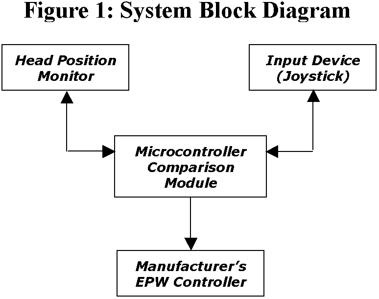 |
After a traumatic brain injury (TBI), many individuals have attending, motor control, and visual processing difficulties that can hinder independent powered mobility [1]. Poor attending and visual processing can make it unsafe to operate an Electric Powered Wheelchair (EPW) without supervised cuing. Dependence upon cued guidance by a person does not encourage independent mobility, and may exceed the rehabilitation services available to the patient. An alternative to therapist cuing is electronic monitoring of the patient that enforces head and hand congruence. This would restrict driving if the patient's head is not oriented toward the direction of travel. The idea behind this research is to encourage a patient's to use their residual vision and motor control to achieve independent mobility. Considering this, our primary objective was to design a control system for an EPW that only permits movement if the patient looks in the same direction pointed to by the joystick. The block diagram in Figure 1 describes the design architecture of the system.
DESIGN APPROACH
The ideal monitoring system would track eye gaze of the patient; however, eye-tracking systems we reviewed were not suitable for EPW mounting. The alternative was to implement a non-stigmatizing head tracking system. In examining options to accurately track head position, various existing technologies were considered. Technologies currently used to track human body movement include ultrasonic sensors, infrared sensors, gyroscopic measurements, and digital Hall effect sensors. We established three main criteria for head tracking technology: 1) absolute head positioning, the tracking system cannot drift during extensive monitoring periods; 2) non-stigmatizing for patient; (e.g. cannot mechanically attach to the head or require a helmet) and 3) immunity to noise potentially in the environments (i.e. ambient light, electromagnetic interference, etc.). A summary of these technologies is shown in Table 1. Only one of the technologies considered, (digital Hall effects sensors) met all criteria.
However, using a digital sensor array requires a sensor for each potential head position. Providing even a limited resolution of 6.35 mm (0.25'' in a 12 x 6'' region) would require upwards of 1000 sensors. This prospective design was not implemented due to its impractical nature. We then considered analog Hall effect sensors instead of digital . Since an analog sensor provides a range of signals that varies with magnet proximity, it is possible to interpolate between sensors. Implementation will be to place a magnet on the rear of the patient's head (clip to hair or use mild adhesive), and triangulate its position with an array of linear analog Hall effect sensors. A small set of sensors (n < 25) can be used to observe the patient's head position.
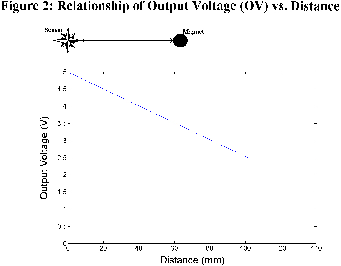 |
To create a triangulation set of sensors, they must be spaced at equal distances. This distance ( D falloff ) is the measure where, beyond this point, the sensor can no longer detect a magnetic field. When a magnet is directly at a sensor, its output voltage (OV) is 5 V. As the magnet moves away from the sensor, the OV linearly decreases to 2.5 V as it approaches D falloff . If the magnet exceeds D falloff , its OV will remain idle at 2.5 V. Experimentally, we determined that a D falloff of 101.6 mm (4'') was suitable; the relationship between OV and distance is illustrated in Figure 2.
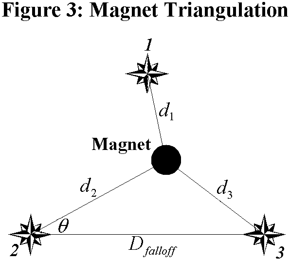 |
For a triangulation to work properly, at least three Hall sensors should detect the magnet within their range of graded response.
 |
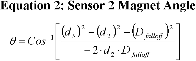 |
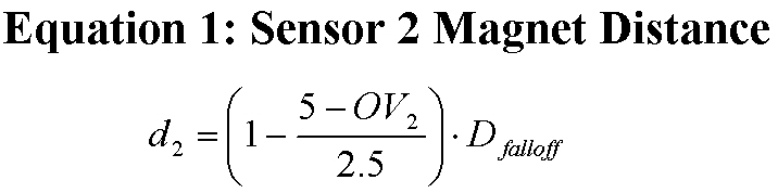
Given the linear sensitivity of the sensors, the magnet distance with respect to sensor 2 is shown in Equation 1. The distance of the magnet from the other two sensors can be calculated in the same fashion. To provide the reference angle with respect to sensor 2 's horizontal, the Law of Cosines is sufficient as in Equation 2. Although sensor 1 is not used in the position calculation, it is needed to determine which triangulation set the magnet is resident. Without this third sensor reference, it would be ambiguous whether the magnet was above or below the horizon of sensor 2 .
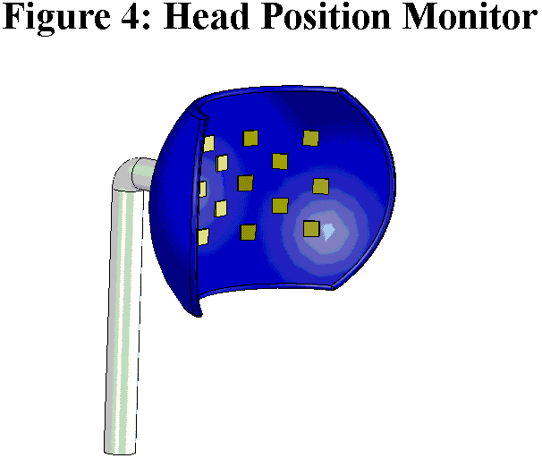 |
The next step is to incorporate the triangulation sets of linear analog Hall effect sensors into the Head Position Monitor (HPM). The HPM consists of two components. The first is an ergonomically designed shell similar to a headrest that positions the sensor set. A computer-aided design (CAD) drawing of this shell is shown in Figure 4 with approximate locations of the Hall effect sensors. The second functional component is the embedded system that monitors the OV of each sensor. The analog output voltages are sampled by an analog-to-digital converter (ADC). The ADC's generate 10-bit digital values linearly proportional to its input voltage.
Ten bits of resolution divides the space between sensors into1024 (2 10 ) discrete steps. With 101.6 mm (4 inch) distance between sensors, the resolution accuracy (RA) can be determined by using Equation 3.
When driving, the patient uses their joystick or other input device (ID) to assert their desired movement. The Algorithm Module (AM) polls both the HPM and IP to obtain current head position and desired movement. If the responses are congruent, then the AM will pass along the command to the EPW controller and the chair will move in the normal fashion. Otherwise, the system remains idle.
CURRENT STATUS
A full prototype of the circuits and sensor array described in this article are now under construction. We hope to have a working model to demonstrate at the conference.
DISCUSSION
A head monitoring system for EPW operation for patients with a traumatic brain injury has the potential to provide improved independent mobility. With the described analysis, the methodology proposed yields a theoretical resolution within a tenth of a millimeter. In addition, the system offers absolute position detection and an acceptable human interface.
REFERENCES
- Niemeier J, The Lighthouse Strategy: use of a visual imagery technique to treat visual inattention in stroke patients, Brain Injury , vol.12, no. 5, pp. 399-406, 1998.
- Kanyer B, Meeting the seating and mobility needs of the client with traumatic brain injury, Journal of Head Trauma Rehabilitation , vol. 7, no. 3, pp. 81-93, 1992.
- Fehr L, Langbein E, and Skaar SB, Adequacy of power wheelchair control interfaces for persons with severe disabilities: A clinical survey, Journal of Rehabilitation Research and Development , vol. 37 pp. 353-360, 2000.
- Rao RS, Seliktar R, Rahman T, and Benvenuto P, Evaluation of an isometric joystick for power wheelchair control, RESNA Press, 1993.
- Melexis Microelectronic Integrated Systems, Retrieved December 5, 2003, from http://www.melexis.com/prodfiles/MLX90215_Rev007.pdf.
ACKNOWLEDGEMENTS
This research is supported by a National Institute of Disability Research and Rehabilitation (NIDRR) Traumatic Brain Injury (TBI) Model Systems Grant
Author Contact Information:
Donald M. Spaeth, PhD,
Human Engineering Research Laboratories
(151R1),
VA Pittsburgh Healthcare System,
7180 Highland Dr.,
Pittsburgh PA 15206,
(412) 365-4850,
spaeth@pitt.edu