The Lifting Assist for a Powered Wheelchair
ABSTRACT
Our client is a seventeen-year-old girl with cerebral palsy. She cannot get into her motorized wheelchair comfortably without the assistance of others. The goal of this project was to build a device that will allow her to ascend into her wheelchair as independently as possible. We achieved this goal by constructing a lifting assist that is used in conjunction with her power wheelchair, which has an 8 extending actuator. The device lifts her 8 off the ground to make sitting in the wheelchair easier; it also serves as a footrest at all times during use of the wheelchair. This novel device will give our client new independence, and minimize the help required from others.
KEYWORDS
Cerebral palsy, lifting assist, actuator, linear bearings, wheelchair
BACKGROUND
Our client has cerebral palsy (CP), a neurological disorder that affects the area in the brain that is responsible for motor skills (1). Her CP is described as quadriplegia with mixed spasticity and athetosis. She has spasticity in both legs and both spasticity and athetosis in her left arm and hand, as well as hypotonicity in her truck. She cannot step backwards and has difficulty balancing herself, and has limited left-hand dexterity. She is five feet tall and weighs about 160 pounds, and because of her height, she has trouble getting back into her power wheelchair (Pride Mobility 1122 Jazzy) after getting out (2).
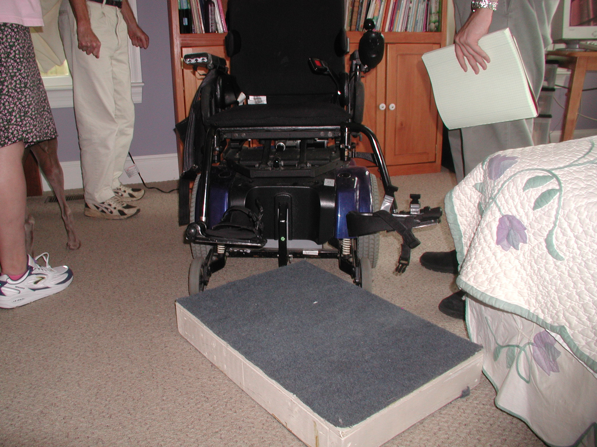
Our client drives her wheelchair independently, and both her physical therapist and her mother felt that she would benefit from a powered lift that helps her get into her chair with less help. Previously, she used a cumbersome five-inch tall stepping block to rise up to a height necessary for her to be lifted into the chair (Photo 1). After sitting down with much assistance, she was shifted backward into her chair until she was comfortable. The five-inch tall block was not portable, and no appropriate commercial devices were found.
 |
|---|
Problem Statement
The goal of this project was to build a device to help our client ascend into her powered wheelchair more independently. Primary objectives included safety, and ensuring that it would not interfere with daily activities such as moving through doorways or fitting under tables. The device also needed to be weather resistant, since our client lives on an active horse farm. Finally, the device had to be aesthetically pleasing, as it would reside on her wheelchair.
DESIGN AND DEVELOPMENT
 |
|---|
During an initial meeting at our client's home with her mother and physical therapist, we developed a list of objectives and constraints. Using these as a guide, we first considered lifting the client using a custom platform and an external linear actuator powered by a DC motor. The platform would replace the wheelchair's footrests, and slide on a linear bushing system attached to the footrest mounting locations. After subsequent visits with our client, we realized the external actuator required space in excess of what was available.
 |
|---|
The second alternative was to use the onboard actuator as the primary lifting instrument. This actuator was easily operated using a switch at the rear of the electric wheelchair and could provide 7 ½ of lift. With ½ of platform thickness (aluminum base + rubber cushion), this method provided 8 of lift. The overall concept was as follows: First, the client would stand on a platform in the lowered position. Second, the seat actuator would be extended, causing the wheelchair seat and platform to raise by 7.5. Third, the platform would be locked into place vertically. Fourth, the seat actuator would be retracted, lowering the seat to its minimum height. At this point, the client would be 8 closer to the seat vertically than she was on the ground. Finally, the client could sit back into the seat.
 |
|---|
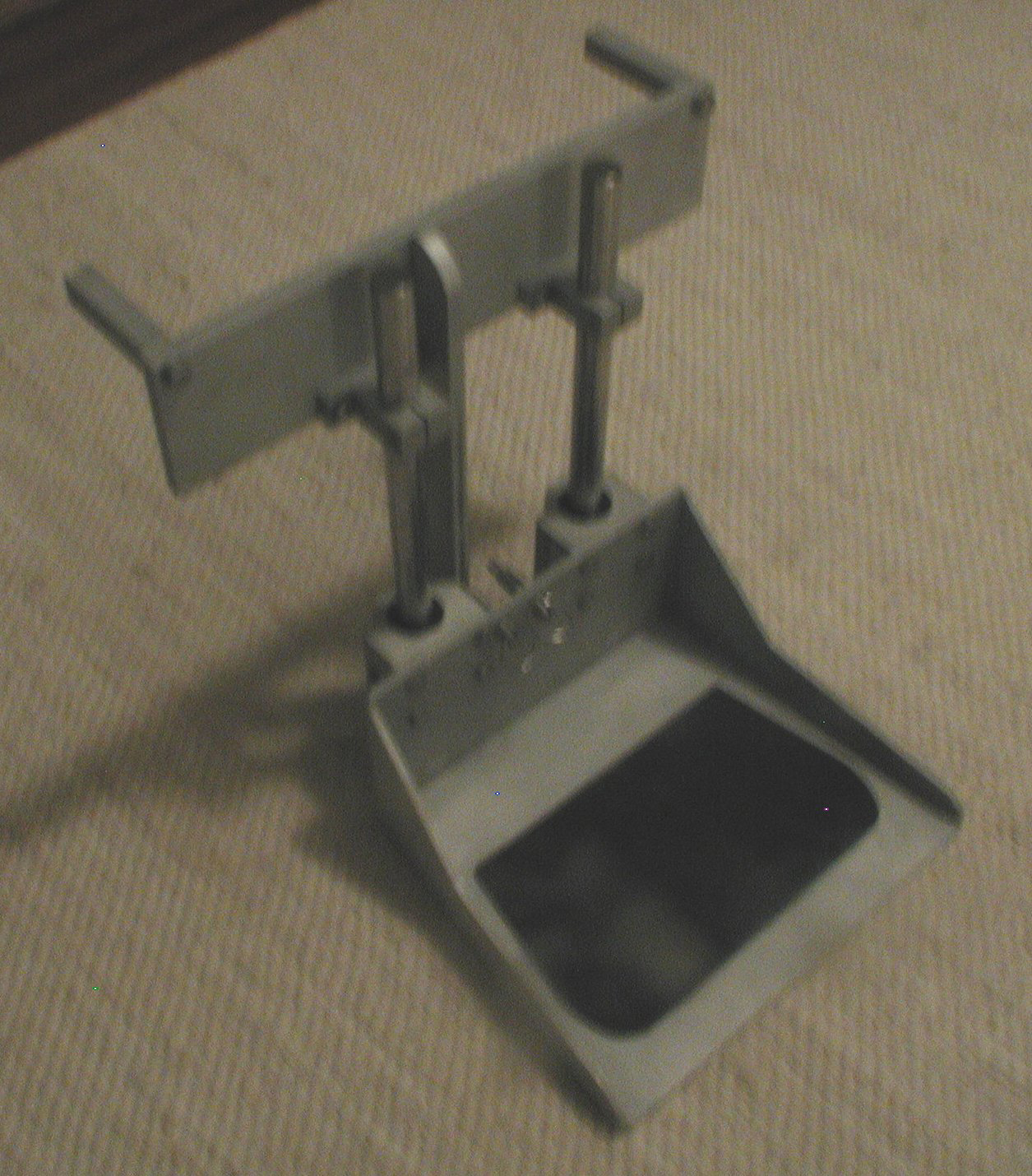
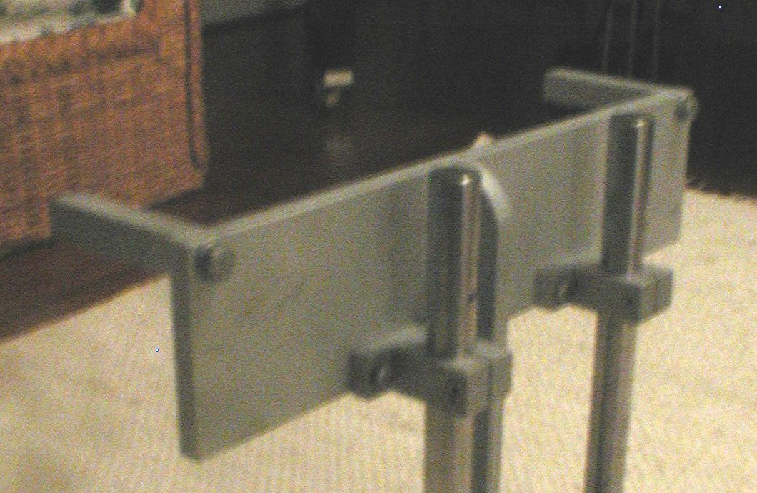
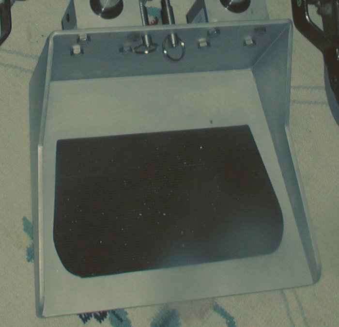
The final design, based on this concept, uses a four-component system (Photo 2) comprised of a mounting component, a linear stabilization component, the platform, and a locking system. The mounting component consists of a rectangular plate, connected by two ¾ square insertion rods to the footrest attachment sleeves below the wheelchair seat. Two shaft clamps and a vertical lock bar attach to the front of the rectangular plate (Photo 3).
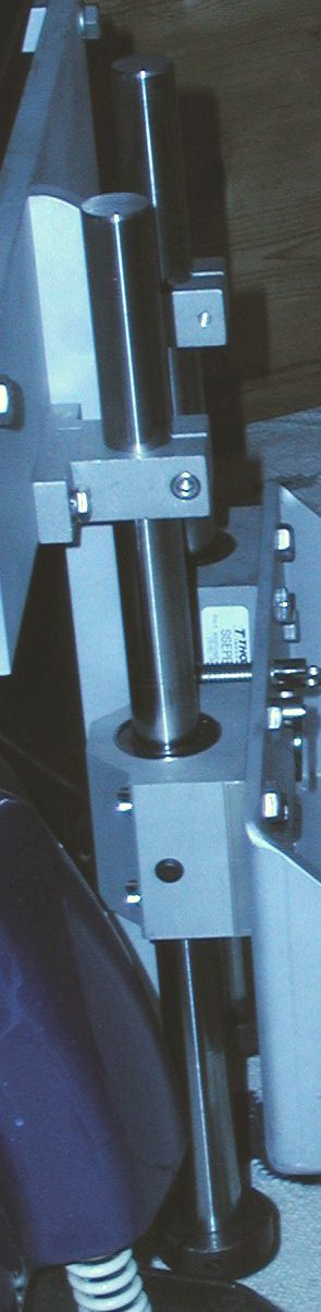
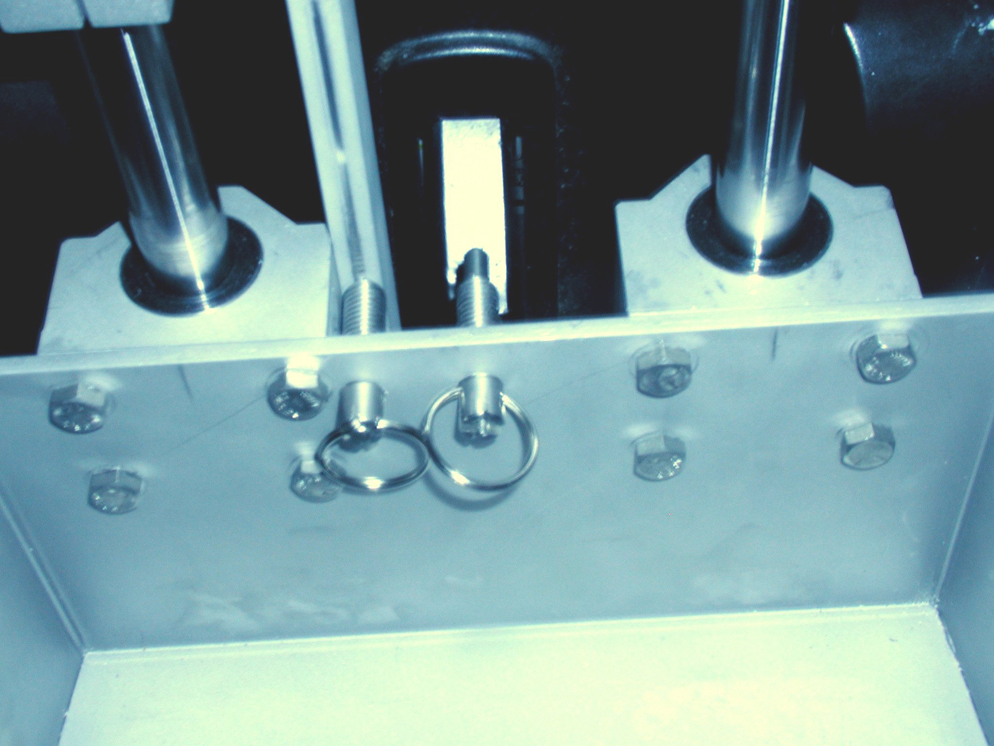
The linear component (Photo 4) includes two 25-mm diameter shafts, the tops of which are secured to the shaft clamps. Two pillow-block linear bushings slide freely on the shafts, and attach to the rear of the platform, allowing it to move vertically. Locking collars mount on the shafts below the bushings, causing the platform to raise as the seat actuator extends. The platform base (Photo 5) has a trapezoidal shape, 12 on the end nearer the wheelchair, 14 on the other end, and 11.5 deep; these dimensions give the client maximum space given the constraints of the wheelchair. The base is covered with a piece of non-slip rubber. The rear of the platform is 12 horizontally by 6 vertically. The platform sides taper from 6 at the rear to 1 at the front; this design provides rigidity yet also gives the client maximum visibility of her feet as she steps onto and off the platform.
The locking system (Photo 6) consists of two spring pins attached through the platform's rear wall. The first spring pin locks into a vertical stationary bar on the wheelchair, originally intended for stationary platform mounting. A custom square rod attaches to the vertical stationary bar, extending its height. As the seat raises to maximum height, this spring pin locks into a track in the vertical stationary bar extension, thus fixing the vertical height of the platform. When the chair is lowered to its minimum height, the second pin locks into the vertical bar attached to the rectangular plate of the mounting component. If the client tilts her chair, this latter spring pin holds the platform in the proper position while the first spring pin slides out from its hole in the stationary bar extension. To get out of the chair, an assistant pulls on the rings of the lock pins, which allows the platform to slide back down to floor level.
 |
|---|
EVALUATION
Upon testing the device, it was determined that the 7 ½ of lift was sufficient for our client to ascend onto the front end of her wheelchair seat. However, this height was not adequate to give our client the ability to push herself into a more comfortable position toward the back of her seat. Nevertheless, the overall effort involved with the lift was far less than that without the lift.
 |
|---|
One of the main concerns was tipping. From a torque analysis, it was determined that if the front wheels were not locked into place, the center of the client's weight could be no further than 3.68 inches from the middle wheel if tipping was to be prevented, an unrealistic expectation. However, when the front wheels were fixed into place, the client's position could be 15.6 from the front wheels, which exceeds the length required for our final design. Empirical testing confirmed this theoretical result.
Discussion and Conclusions
The lifting assist meets its functional objective. While she still needs assistance for balance and safety when the lift is in operation, the device lessens the burden of physical exertion to a more acceptable level. The lifting assist can be reproduced and is adaptable to a wide range of potential users. Because it uses a simple two-post mounting method, it does not require modifications to the wheelchair and can easily be removed and replaced with the original footrests if necessary.
The main limitation of the lifting assist is that it requires an assistant to manually disengage the spring pins to move the platform to its resting position on the ground. In the future, these spring pins can be replaced with solenoids, so that this can be done with a user-controlled switch. We demonstrated the lifting assist for our professor, classmates, supervisors, and others familiar with occupational therapy and rehabilitation engineering. The statement we received from our client's physical therapists reads, the finished product will enable only one person to assist (her) instead of two because they will not have to lift her. Also, more people will be able to assist (her) for instance, her sister who is smaller than her mother and other friends who don't have special training. It will also give (her) more independence in the future (when she is) away at college and in a more independent living situation in a dorm or apartment. It will also assure that those helping her will not have to risk back injuries.
We are still testing the device with the client to insure its safety and efficacy. Further work will involve developing methods for ensuring safety in all wheelchair modes, and modifying the platform to provide a more comfortable resting foot position. When completed, we believe it will improve our client's independence, and minimize the physical exertion required from others to help her ascend into her chair.
REFERENCES
- United Cerebral Palsy. September 17, 2003. < http://www.ucp.org/ >.
- Pride Mobility Products. October 2, 2003. <http://www.pridemobility.com/>.
ACKNOWLEDGEMENTS
Throughout this project, we garnered help from many people. From the Duke University Biomedical Department, we thank Associate Professors Roger Nightingale and Marcus Henderson. We also appreciate the help of our client's physical therapist Nancy Curtis as well as our client's mother. From National Health Care Services, Larry Lankford and Jim Dellehay were extremely helpful, and we are also very grateful for their donation of parts for this project. From the Biomedical Machine shop, Joe Owen provided a valuable service. We would also like to extend a special thanks to Mickey Roberts, Duane Cartwright and Wayne Buchanan from the Duke University Medical Instrument shop for their diligence, precision and efficiency on our platform and mount. The BME 260 Teaching Assistant, Mark Palmeri, was extremely resourceful and was always willing to lend a hand. Finally, we would like to thank Dr. Laurence Bohs of the Duke Biomedical Department who provided inspiration, guidance, and knowledge that included and surpassed the realm of this project. This material is based upon work supported by the National Science Foundation under Grant No. 0118558.
PRIMARY AUTHORS
Andrew Steinberg
9 Bristlecone Way
Augusta, GA 30909
Paul Lisi
5 Cornelius Place
Massapequa, NY 11758