Envelope Inserting Aids
ABSTRACT
Several devices have been developed to help individuals with disabilities insert documents into envelopes of different dimensions. Each device holds an envelope in a document receiving position and aligns paper prior to insertion. Envelope insertion is then achieved through single-hand pushing actions. The devices are relatively inexpensive, portable, easy to operate and suitable for use by individuals who lack fine motor control.
KEYWORDS:
envelope insertion; envelope opening; paper alignment; workplace equipment
BACKGROUND
Orange Enterprises, Inc. is a non-profit agency in Hillsborough, North Carolina that meets the employment needs of citizens with disabilities by subcontracting businesses in areas of mailing and packaging. Employee salary is a function of competence in areas of mail preparation, such as document collation and envelope stuffing. While collation can be achieved with minimal single-hand control, employees with cerebral palsy have difficulty performing fine motor tasks like envelope insertion. Cerebral palsy is a chronic neurological condition that affects the communication between the brain and the muscles, causing a permanent state of uncoordinated, involuntary movement and posturing (1).
Commercially available devices for mass mailing are fully automated to dispense documents onto conveyor belts, align paper using pusher fingers and to feed collations into envelopes that are held open by various throat-opening mechanisms (2). Such systems are predominantly utilized in large business settings and cost on the order of thousands of dollars. Though efficient, commercial devices eliminate employees from the mailing process. A simpler manual device is needed to help employees align documents and stuff envelopes as independently as possible.
PROBLEM STATEMENT
This project's goal was to design envelope inserting aids that open an envelope for receiving documents and align collations for insertion. Four sizes of envelopes were to be accommodated: a (10 ² x 13 ² ) , b (9 ² x 4 ² ) , c (9.5 ² x 12.75 ² ), d (9 ² x 6 ² ). Important objectives included negligible damage to envelope and contents, sufficient throat opening and alignment capabilities for collations of variable thickness, adaptability to envelopes of different dimensions, portability, ease of operation and safety.
RATIONALE
Providing Orange Enterprises with these devices will enable some employees to perform a task that had not previously been possible for them. Besides enhancing productivity at the workplace, the Envelope Inserting Aids will increase employee pay and engender independence and self-confidence. The device are also simple to construct and cost effective, allowing for easy reproduction to benefit a larger employee base.
DESIGN AND DEVELOPMENT
Throughout the design of the device, we consulted with our supervisor at Orange Enterprises to discuss our approach and to assess the clients' needs. Through an initial meeting with our clients and supervisor, we learned that employees are paid according to the number of envelopes inserted, that job coaches are available for assistance, and that clients could perform single-handed pushing actions easily.
 |
Our preliminary design involved an envelope holder and an adjoining aligning device (Photo 1). The holder had a pressure plate biased by a leaf spring upon which a stack of envelopes was placed. Fixing one edge onto an overhead ledge opened the top envelope. After document insertion, the envelope was removed through a gap in the end member, and the pressure plate pushed the next envelope up into position. The aligner consisted of a platform with side members leading to the envelope throat. Staff members at Orange Enterprises helped to mount and dismount the envelopes, and positioned collations on the aligner for clients to slide into the envelope using his hand or a stick with a rubber tip.
 a (10 ² x 13 ² ) |
 b (9 ² x 4 ² ) |
 c (9.5 ² x 12.75 ² ) |
 d (9 ² x 6 ² ) |
Upon testing the prototype, we found that this design was ineffective as paper often snagged on the interfaces between the aligner and holder, as well as on the edges of the open envelope. The overhead ledge obstructed full document insertion, and the device needed firmer mounting on the work surface during operation. The elevated aligner platform also made it difficult for employees to reach the paper, since wheelchair arm supports limit the level to which workers can be raised relative to the table surface.
 |
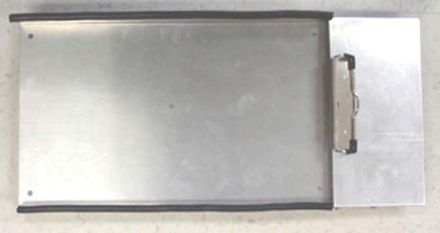
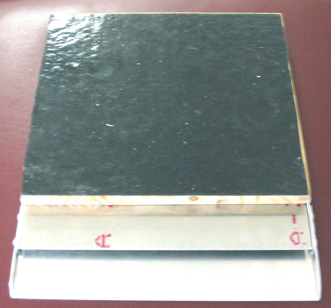
These constraints were considered in our final designs of four envelope-inserting aids for different envelope dimensions (Photo 2 a , b , c , and d ). Each device consists of an aluminum aligner tray mounted on a plywood base. The tray has perpendicular or angled edges to align documents (Photo 2 a , d ). Some perpendicular edges have an additional lip to ensure that documents stay on the tray (Photo 3, 2 b, c ).
 |
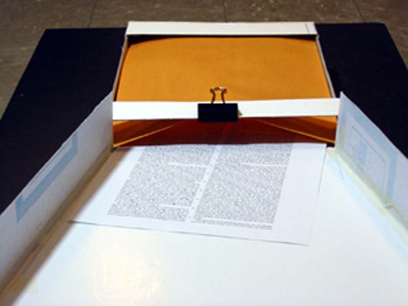
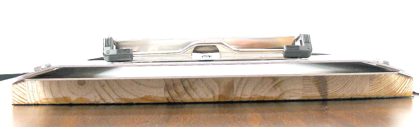
The tray and its edges extend a few inches beyond the plywood. A ledge is mounted over the tray extension, and the gap between the ledge and the tray forms a channel for documents into the envelope (Photo 4). The envelope is opened by pulling it over the rigid channel and secured with a clip. The top piece of the channel extends further into the envelope to provide stability, while the tray extension is shorter so that documents will not remain in the channel upon envelope removal (Photo 5).
 |
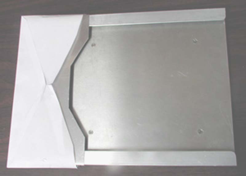
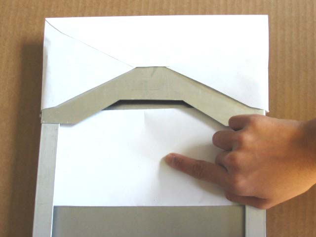
The shape of the channel is customized for each envelope. For business envelopes with triangle flaps [ b (9 ² x 4 ² )], the channel's top piece has a triangular cut in the middle to enable the client to reach deeper and insert documents completely (Photo 2 b ). Envelope d (9 ² x 6 ² ) requires a trapezoidal channel with a wider bottom to accommodate snug-fitting documents (Photo 6). The channel is elevated from the work surface by the plywood, so envelopes can be mounted without moving the device (Photo 4).
 |
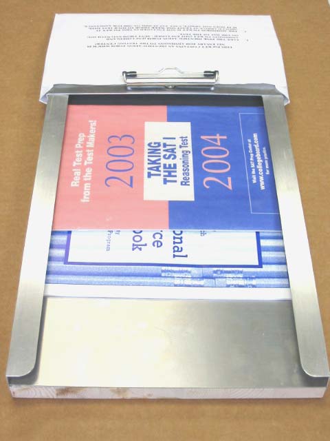
Documents on the aligner tray can then be pushed into the envelope through the channel (Photo 7). Aluminum edges are smoothed and rounded to ensure they do not cut. Edges without a lip are fitted with rubber hoses to minimize stress injuries to the wrist (Photo 2 a ). A piece of Dycem Ò is attached to the underside of each device to secure it to the table surface during operation (Photo 8).
 |
EVALUATION
The main priority of the Envelope Inserting Aids is consistent insertion of documents into envelopes without damaging mail materials or envelopes. After testing the devices with our clients, we determined that aligner edges were effective in keeping paper in the tray. The channel aligns documents properly and the smooth continuous tray extending into the envelope minimizes snagging to allow proper document insertion. The envelope is secured with a clip and does not get displaced by pushing actions. Physical discomfort during envelope insertion is minimized since thin edges of the aluminum (without a lip) are padded. We determined the static and kinetic friction between paper and aluminum to be a small value that increases with contact pressure. Hence the most efficient manner to use the device is to push papers against the tray lightly. With more practice, our clients will be able to use the device in the most efficient manner possible. It may also require the staff at Orange Enterprises some practice to mount and dismount envelopes efficiently.
DISCUSSION AND CONCLUSIONS
 |
Major advantages of the Envelop Inserting Aids include the ability for clients to insert envelopes with simple pushing actions, and their portability, durability, and low cost. The average cost of materials for each device was less than $25. A disadvantage of the devices is that our clients still require assistance for envelope insertion; however, employees are paid according to the number of envelopes inserted regardless of any help rendered. Another disadvantage is that separate devices have to be custom made for other envelopes of different dimensions. Future work could include devising methods for automated envelope positioning and removal, as well as collation placement; or a means of making the client more independent during envelope insertion. The Envelope Inserting Aids have met our objectives, and will allow workers to accomplish a task that they could not complete before.
REFERENCES
- National Institute of Neurological Disorders and Stroke (NINDS) Cerebral Palsy Information Page, 2001 Jan, http://www.ninds.nih.gov/health_and_medical/disorders/cerebral_palsy.htm .
- Marzullo et al. Pitney Bowes Inc., Envelope Opening Apparatus, U.S. Patent 5191751. 1993 Mar.
ACKNOWLEDGMENTS
This material is based upon work supported by the National Science Foundation under Grant No. 0118558. We would like to thank our supervisors, Judy Stroupe and Dayson Pasion, for their input on how to best build a device to help our clients at Orange Enterprises. We would also like to thank Joe Owen who machined the devices, and John D. Finan for helping us with the experimental setup for quantitative analysis of friction. Finally, we would like to thank Dr. Laurence Bohs, our professor, for providing immense guidance and thoughtful ethics lectures.
Author Contact Information:
Shin Yeu Ong
P.O. Box 94481
Durham, NC 27708
Shin Rong Ong
P.O. Box 94536
Durham, NC 27708