Composite Sensor for Drop-off detection in Intelligent Mobility Aids
ABSTRACT
We propose a robust methodology for detecting drop-off and ramps. A combination of infrared and sonar sensors were evaluated under different surface and environmental conditions for their ability to detect (and distinguish) drop-offs and ramps in real time. Results indicate that drop-offs, ramps and short obstacles can be detected reliably and cost effectively.
KEYWORDS
Drop-off, Infrared Sensor (IR), Ultrasound Sensor (Sonar), Intelligent mobility Aids(IMA), Composite Sensor (CS).
BACKGROUND
More than 48% of wheelchair-related injuries are caused by ramps, inclines, curb cuts, changes in surface, or stairs [1]. While most Intelligent Mobility Aids (IMAs) are able to detect upright obstacles (e.g., walls, furniture, and people), few can detect drop-offs. The most popular solution is the Sick laser rangefinder [5], but issues of cost and size make them impractical for inclusion in low-cost mobility aids. We propose a novel approach based on overlapping, low resolution sonar and infrared rangefinders.
RESEARCH QUESTION
Our goal is to replicate the drop-off detection performance of a laser rangefinder [5] using multiple, overlapping, low-resolution proximity sensors, including Sharp GP2D12 and GP2Y0A02YK infrared rangefinders and Daventech SRF08 sonar sensors [2, 8]. There are several classes of failures and errors associated with the sensors [3] but the most critical are Sensor Hidden Failures (SHF) and Sensor Idiosyncrasies (SI) [7]. SHFs occur when a sensor ceases to interact with the environment, but continues to return measurement values. For example, when obstacles are too close to a sonar sensor, an SHF occurs because the sonar sensor is unable to reset itself quickly enough, after generating the acoustic signal, to read the resulting echo. SIs are caused by limitations of a sensor's mode of interaction with the environment. For example, an SI occurs when the light emitted by an infrared rangefinder is absorbed by a dark material or passes through a transparent material.
METHOD
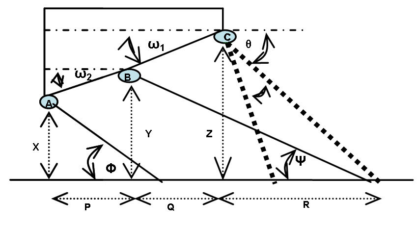 |
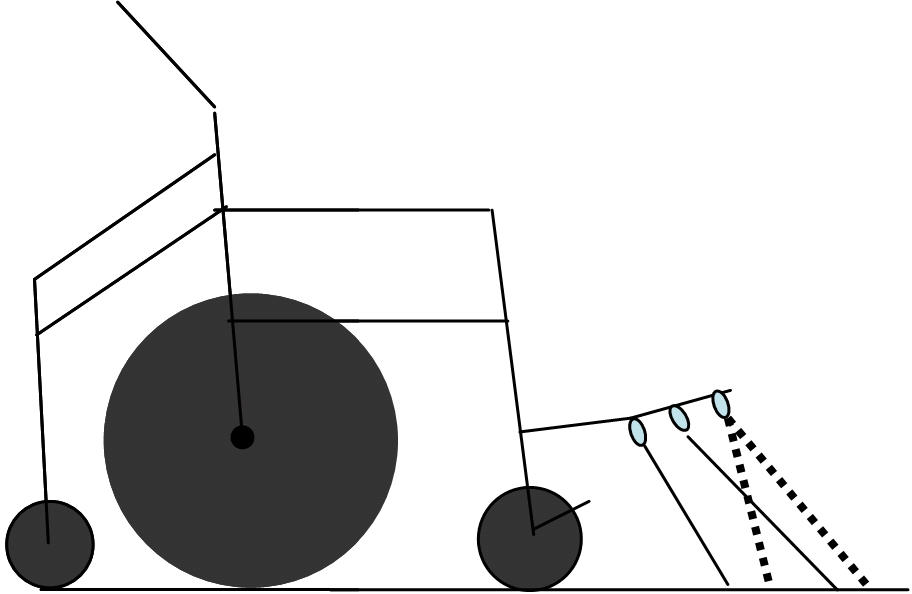
The integration of multiple, overlapping, low resolution sensors is a common approach to coping with the limitations of any single sensing modality [3]. In particular, sonar and infrared sensors are frequently combined due to their low cost and complementary nature [2]. As shown in Figure 1, we use an arrangement of two infrared sensors and one sonar sensor to detect drop-offs. The sensors are mounted on the wheelchair's footrest, as shown in Figure 2, and arranged such that their fields of view overlap.
 |
The drop-off detector identifies inconsistencies both within a single set of sensor readings and over multiple sets of readings by using information from the sensors mounted on both of the wheelchair's footrests. This information is used to develop a statistical profile of the drop-off detector's performance which is then used to assign a confidence value to the detector's output.
RESULTS
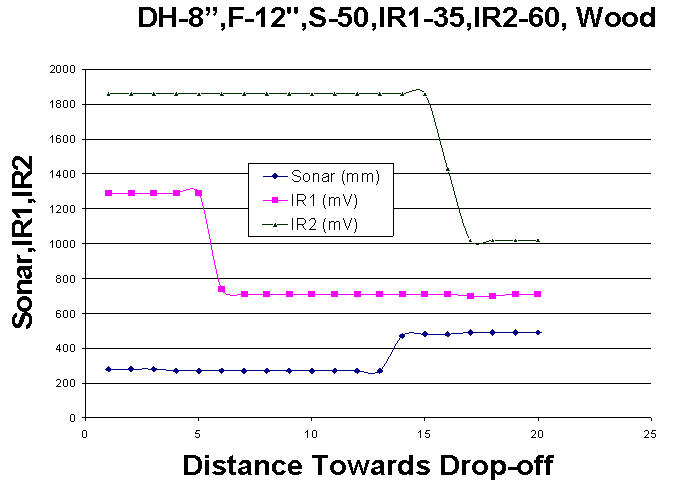 |
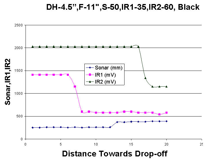
The drop-off detector has been tested on a range of drop-off depths (10cm to 20cm), ramp angles (0 to 22 degrees) and floor surfaces. Accuracy and field of view are optimized when IR1 (in the middle of the footrest) is positioned at an angle of 35 degrees, IR2 (at the rear of the footrest) is positioned at an angle of 60 degrees and the sonar sensor is positioned at an angle of 50 degrees.
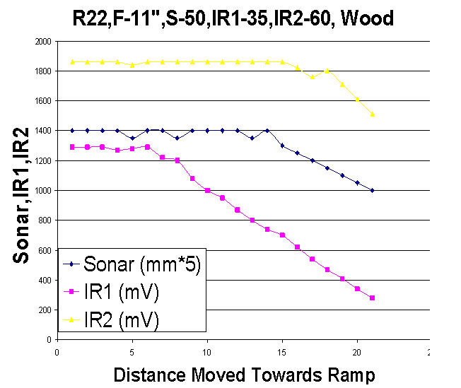 |
Figures 3, 4 and 5 show the performance of the drop-off detector under three different conditions. Figure 3 shows the sensor readings as the drop-off detector approaches a 20cm drop-off on a rough flooring material (wood). As expected, the readings from IR1 and IR2 drop as they detect the drop-off and the readings from the sonar sensor rise. Figure 4 shows the readings from the same configuration of sensors as the drop-off detector approaches the top of a wooden ramp at an angle of 22 degrees. In this situation, the IR sensor readings slowly drop-off (as expected) but the sonar sensor readings fail to rise because the steep angle of the ramp prevents the acoustic signals from echoing back to the sonar sensor. Finally, Figure 5 shows the readings that are obtained when approaching a 10cm drop-off on a dark flooring material that absorbs some of the light emitted by the infrared rangefinders. In this case, the sonar sensor functions as expected, but the readings from the infrared rangefinders exhibit greater fluctuation than normal.
 |
DISCUSSION & FUTURE WORK
Based on the results of preliminary testing, the drop-off detector appears to be an effective solution for a variety of environments. However, it is still possible to envision situations in which both the sonar and infrared sensors would fail simultaneously; for example, a ramp constructed of a light-absorbing material with an angle of descent greater than 20 degrees.
The distance needed by a wheelchair to come to a stop once the user has released the joystick can vary greatly depending on the speed and weight of the wheelchair and the surface material and slope of the floor. Since the stopping distance of the wheelchair must be shorter than the distance at which drop-offs can be detected, the maximum speed of the wheelchair is constrained by the distance at which drop-offs can be detected. Options increasing the detection distance include positioning the sensors higher (perhaps on the wheelchair's laptray or above the user's head) or further in front of the wheelchair (by extending the footrests). However both of these approaches may detract from the appearance of the wheelchair, and increasing the height or length of the wheelchair may make it difficult to fit into some areas.
Presently we are working on the Statistical Model to make the Composite Sensor readings more reliable in observing the Sensor Idiosyncrasies and Sensor Hidden Failures.
REFERENCES
- R. Lee Kirby RL, Stacy A. Ackroyd-Stolarz SA. Wheelchair Safety-adverse reports to the United States FDA. American Journal of Physical Medicine and Rehabilitation .Vol. 74,No.4,July/August 1995 pp. 308-312.
- LoPresti EF, Simpson RC, Miller D, Nourbakhsh I. (2002). Evaluation of Sensors for a Smart Wheelchair. Proceedings of the RESNA 2002 Annual Conference. pp. 166-168.
- Angelo M. Sabatini, Vincenzo Genovese. Composite Proximity Sensor Array for mobility aids. Proceedings of the RESNA 1995 Annual Conference. pp. 487-489.
- Levine S, Bell D, Jaros L, Simpson R, Koren Y, Borenstein J. (1999). The NavChair Assistive Wheelchair Navigation System. IEEE Trans on Rehab Eng. 7(4):443
- Donna L. Kelly. The Enhancement of mobility for individuals who are both physical and visually disabled. Proceedings of the RESNA 1999 Annual Conference. pp. 227-229.
- Yoder J, Baumbartner E, Skaar S. (1996). Initial Results in the Development of a Guidance System for a Powered Wheelchair. IEEE Tran on Rehab Eng. 4(3):143-151.
- Daryal Thomas. A Robust, Self Diagnosing Sensing Methodology for application to Smart Wheelchairs. Proceedings of the RESNA 1994 Annual Conference. pp. 466-468.
- Stephen T. Hayashi , Edmund F. LoPresti, Richard C. Simpson, Illah Nourbaksh, David Miller (2002) An expensive, alternative drop-off detection method Proceedings of the RESNA 2002 Annual Conference .
ACKNOWLEDGMENTS
This research is funded by a Phase I Small Business Innovation Research grant from the National Eye Institute (#1R43EY014490-01).
Author Contact Information:
Vinod K. Sharma, MS,
University of Pittsburgh ,
5065, Advanced
Rehabilitation Technology Lab Forbes Tower ,
Pittsburgh,PA-15260,
Office Phone (465)-383-6795
EMAIL: vks3@pitt.edu