Hardware Design of the Smart Power Assistance Module for Manual Wheelchairs
ABSTRACT
The Smart Power Assistance Module (SPAM) consists of a pushrim activated power assist wheelchair (PAPAW) hubs combined with movement control and obstacle avoidance components. The hardware design of the 2 nd Generation SPAM is described. The goals of this design iteration were to reduce the number of additional components, produce an electronics board that includes movement and obstacle avoidance functions, and select and mount sensors for obstacle detection.
Keywords:
Obstacle Avoidance, Pushrim-Activated Power Assisted Wheelchair, Yamaha JWII, Visual and Physical Impairments
INTRODUCTION
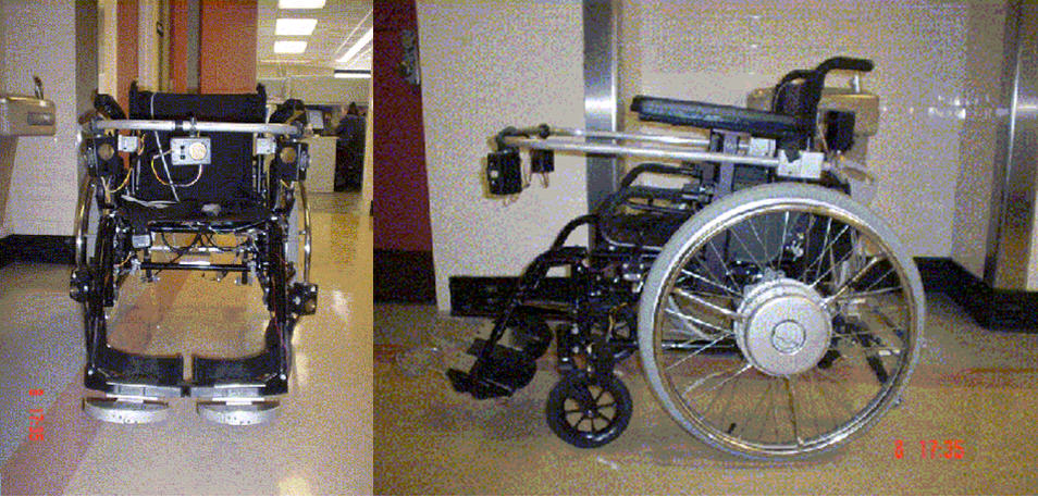 |
Several studies have found that propelling manual wheelchairs can cause fatigue and upper-extremity repetitive strain injuries (UE-RSI) for their operators [1][2]. In response to this problem, pushrim activated power-assist wheelchairs (PAPAWs) have been developed and introduced into the marketplace [3]. PAPAWs offer a viable alternative for individuals, who are at risk for UE-RSI, have low cardiovascular reserves, or who have marginal ability to functionally propel a manual wheelchair. Power assistance is being used as the basis for a Smart Power Assistance Module (SPAM) that provides independent mobility to non-ambulatory individuals with visual impairments by detecting obstacles near the wheelchair and using the motorized hubs to avoid these obstacles. The first generation (SPAM), (Figure 1), was based on standard original equipment manufacturer (OEM), Yamaha Motor Corporation, JWII, drive train and controller components combined with our control and obstacle avoidance hardware [4]. In the second generation SPAM, we have used the same hubs (rotary transformer, linear compression springs, potentiometer, ring gear); however, we developed custom electronic circuitry (microprocessor, motor driver), and sensors for movement control and obstacle avoidance functions. This approach allows us to provide much smoother and more robust control of the PAPAW. In addition, a SPAM could be useful for individuals who experience difficulty in moving a wheelchair inside a van, or in other confined spaces such as elevators and bathrooms.
METHODS
STATEMENT OF THE PROBLEM
The SPAM was designed for individuals with visual and physical impairments who are marginal manual wheelchair users, and for individuals who have navigation problems in restrictive spaces. The goals for the second generation prototype were to reduce the number of additional elements, to incorporate more effective sensor technology and to develop a custom electronic system that provides open access for programming movement control and obstacle avoidance functions.
DESIGN
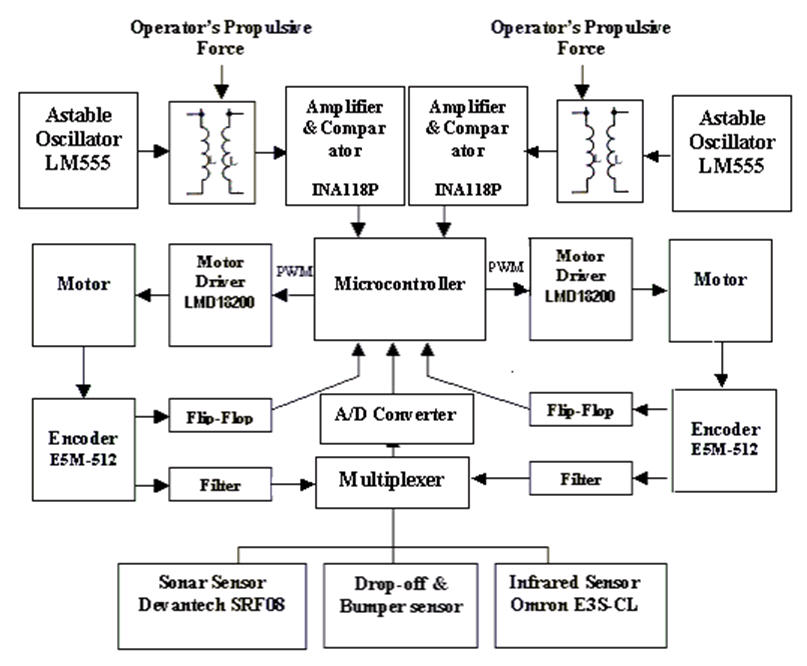 |
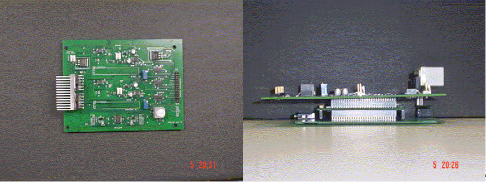
The electronic hardware was based upon the Tattletale Model 8 electronic board (which include the MC68332 microcontroller), interfaced to our custom board design to provide sensor interfacing (propulsive force sensing circuit, speed and direction identification circuit, obstacle avoidance circuit) and a power amplifier for the motor drives (Figure 2, Figure 3). The optical and ultrasonic sensors were also packaged for use on the SPAM. (Figure 2) The obstacle avoidance circuit includes 14 sensors (7 sonar, 7 infrared), which are mounted to the auxiliary aluminum bar. This SPAM design is able to sense the propulsive force applied to each rear wheel of the wheelchair, the velocity of each rear wheel, and the location of obstacles relative to the wheelchair.
 |
Several types of sensors have been integrated into the SPAM. These sensors are used for tracking the state of the wheelchair (e.g., torque applied to each rear wheel by the user, and wheel velocity), and locating obstacles in the wheelchair's environment. Information from all sensors is collected by a microprocessor, which integrates information about the user's input and the surrounding environment, and passes command signals to the motor drivers.
1. The Propulsive Force Sensing Circuit
The pushrim torque applied to the hubs is translated by sets of linear compression springs, and this force is transduced by a potentiometer. The output from the potentiometer circuit on the rotating portion of the wheel is transmitted to the stationary part of the wheelchair by modulating the primary coil signal that excites the secondary coil on the stationary side. An LM555 timer in astable mode is used to create the carrier signal for the primary coil. The modulation frequency was set at 10 kHz AC signal. The output signals of the coils go to the INA118P instrumentation amplifier. This electronic circuit is used for sensing the speed and direction of each rear wheel.
2. Detection Methods of Speed and Direction
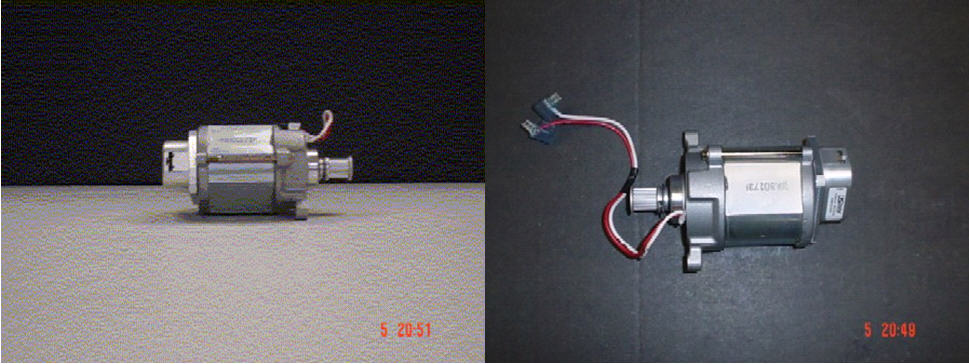 |
The velocity of each DC motor is detected by optical encoders (E5M-512-250) mounted directly to each motor shaft. This solution reduces encoder vibration, and provides a cleaner feedback signal. (Figure 4) The encoder channel A, and channel B together detect the motor rotation direction and provide feedback to the microcontroller. When channel B signal is leading, the (Cp) clock input of a flip-flop and the signal from the channel A will be read in, when the clock signal rises. Because there is a 90 degree different between the two channel signals, a signal from channel A signal will be read in a high (1) signal in this case, that means the motor is rotating counter clockwise. On the contrary, when the motor rotates clockwise, the channel A signal will lead resulting in channel A being read as a low (0) signal to the flip-flop. Channel A is used for detecting the speed of the motor. The output signal frequency of the encoder is converted to motor rotation speed. For speed detection a high-frequency filter is employed. The output of the filter is interfaced to the A/D converter of the microcontroller.
3. The Motor Driver
The LMD18200 is a 3A H-Bridge designed for motion control applications, and accommodates peak output currents up to 6A. This chip provides the speed and direction control of the DC motor during PWM (Pulse Width Modulation) control. The PWM switches the power on and off in a series of quick pulses at a frequency of 20 KHz. PWM signals from the microcontroller are connected to the motor drivers (LMD18200).
4. Obstacle Sensors Selections and Their Mounting
Obstacles are identified using infrared rangefinders (Sharp GP2D12, Sharp GP2Y0A02), sonar sensors (SonaSwitch, Devantech SRF08), and bumper sensors. (Figure1). The sonar sensors have a maximum range of 4000mm and a minimum range of 150mm. Infrared range finders provide a focused, highly modulated infrared beam. The result is an accurate range value between 100mm to 800mm (GP2D12), and between 200mm to 1500mm (GPY0A02) in a variety of circumstances. 14 sensors (7 sonar, 7 infrared) are mounted to the wheelchair's frame and an aluminum bar mounted on the wheelchair at arm-rest high. Future design should incorporate sensors into the chair frame, and auxiliary frame (plastic or fiberglass) in a more discrete manner. The sensors outputs are connected to the microprocessor via a multiplexer.
RESULTS
Each sub-system of the hardware was tested and worked to specifications. The next task of the SPAM project is to implement more sophisticated movement and obstacle avoidance software. In the future, new sensor technologies that are less prone to signal corruption and distortion will be investigated. We are currently exploring the use of infrared sensors for detecting drop-offs (such as curbs and descending stairwells) as well as obstacles. Clinical trials are planned in which individuals with visual impairments will use the SPAM for laboratory-based trials and extended field trials.
REFERENCE:
- Davidoff, G., Werner, R., Warning, W. Compressive mononeuropathies of the upper extremity in chronic paraplegia. Paraplegia (1991) 29:17-24
- Nichols, P.J.R, Norman, P.A., Ennis, J.R. Wheelchair user's shoulder? Shoulder pain in patients with spinal cord lesions. Scand J Rehab Med (1979) 11:29-32
- Cooper, R., Fitzgerald, S., M. Boninger, Prins, K., Rentschler, A., Arva, J., and O`Connor, T. Evalation of a pushrim activated power-assisted wheelchair. Archives of Physical Medicine and Rehabilitation, (2001) 82(5): 702-708
- Simpson, R., LoPresti, E., Hayashi, S., Guo, S., Ding, D., Cooper, R. Smart Power Assistance Module for Manual Wheelchairs. Proceedings of the RESNA 26 th International Annual Conferences, Atlanta, GA (2003): 1-5
ACKNOWLEDGMENTS
This research is funded by a Phase I Small Business Innovation Research grant from the National Eye Institute (#1R43EY014490-01).
Author Contact Information:
Roland Frisch B.S.
Address: 2051 Biatorbagy, Szabadsag ut
20., Hungary
(+36) 20 312 0059; Email: roland1@freemail.hu ,
roland1@pro.hu