Design to Add Body-Powered Functionality to the International Red Cross Above-Elbow Prosthesis
N Bhise, R Carlisle, S E Huber, and W J Richardson
Abstract
As a result of landmine accidents, mutilation by rebel groups, and poor healthcare systems, there is an increasing number of upper-arm amputees in developing countries. Prostheses currently available are not adequate due to high expense and complex design. This paper presents a design of an above-elbow, body-powered prosthesis for use in developing countries. The design focused on maintaining low cost, simple design technology, using locally available materials, and providing a wide range of functionality. A body-powered cable/harness system and locking mechanism were designed to enhance the function of the prosthetic arm distributed by the International Red Cross in developing countries. Prototype testing validated the design as an inexpensive, safe, simple and functional solution.
Keywords:
Upper-arm prosthesis; developing countries; body-powered; above-elbow amputees
Background of Problem
The population of above-elbow amputees in developing countries is approximately 1 amputee per 500 citizens (1). This is the result of a high incidence of infections and accidents, poor medical resources, and mutilation by rebel groups. In countries like Sierra Leone and Dominican Republic, the majority of the work force is involved in manual labor with agriculture being the major source of income. In these countries, amputees are limited in employment opportunities. Without their ability to generate income, chances of gaining social status are curbed and they remain in poverty. Many of the prosthetic designs available on the market are complex in their materials and technology, resulting in high cost. Amputees living at or below the poverty line cannot afford to buy their own prosthesis and instead must rely on one donated by nonprofit organizations that lack in their range of motion and function. Hence, a fully functional prosthesis is not widely available to all amputees.
 Figure 1. International Red Cross Arm. Prosthesis distributed by Red Cross is manufactured by CR Equipements in Coppet, Switzerland. (Click for larger view)
The prosthesis distributed by the International Red Cross (Figure 1) consists of a forearm, elbow joint with locking holes and pin, and a socket to slip over the residual limb. The arm is simple and low cost but it is disadvantaged in that the operation of the prosthesis is dependent upon the user’s other arm.
Our goal was to develop an inexpensive above-elbow prosthesis that provides basic motion for amputees in developing countries. The original aim was to design the whole system, but shifted to focusing on improvement of the IRC arm as an acceptable base. The team plans to design a prosthesis in which the activation of the elbow lock and movement of the arm will be controlled by a cable system, giving it independence from the other arm. The design should use local fabrication methods and materials to minimize manufacturing costs. Also, it should allow the amputee to perform everyday activities and be durable, comfortable, and culturally accepted. The specific design constraints included supporting a load at different locked positions, locking capabilities in at least three different positions, maintain safety, durability, and affordability. Important aspects of the prosthesis identified for design analysis included the locking mechanism, and the harness and cable system. The socket and terminal device design were not considered because the available designs were adequate.
Design Alternatives
To generate alternatives for the design, the team visited local prosthetic labs and interviewed amputees to research commercial prostheses, fabrication methods, and technology. Alternatives were analyzed according to the objectives and constraints to select the design for prototyping. For the locking mechanism, the alternatives evaluated included a manually controlled lock, a cable controlled body-powered lock, and a lock powered by an electrical solenoid. All of these types were able to slide a pin into a slot in the elbow, locking it into position.
Cables and harnesses can be used to achieve elbow motion and actuate the locking mechanism. Several different alternatives exist concerning the body motions, harness design, and cable location/ attachment. A harness can vary in the body motions employed such as shoulder shrugs, back stretches, and arm or leg pulls. The cable can be positioned in several ways which include: inside the arm, outside the arm, and through flexible guides which hold the cable close to the prosthesis.
Crude evaluation of the alternatives was performed using comparison matrices and basic design knowledge. An example comparison matrix for the locking mechanism is seen in Table 1. From the analysis, it was decided that a combination manual/ cable control lock was the most effective design. The cable-control mechanism will be used as the primary mode of activation and the mechanical manual control knob will act as a safety backup to increase the load carrying capacity, when needed. Running the cable down the inside of the upper-arm section is more aesthetically appealing, but requires entry and exit out of the arm, complicating the design. Also, it would not be able to provide the necessary torque to accomplish the elbow rotation. Therefore, a cable attachment outside the arm using simple screws or hooks was selected. Since the muscle motions used should be simple and not interfere with other common body movements, motion of the back was the most effective alternative.
Design alternative |
Constraint |
||||
|---|---|---|---|---|---|
Affordability |
Safety |
Manufacturability |
Comfort/Ease to Use |
Functionality |
|
| Mechanical Manual Control | √√ |
√√ |
√√ |
√ |
|
| Mechanical Cable Control | √ |
√ |
√√ |
√√ |
√√ |
| Electric Solenoid Control | √ |
√√ |
√√ |
||
Prototyping and Testing
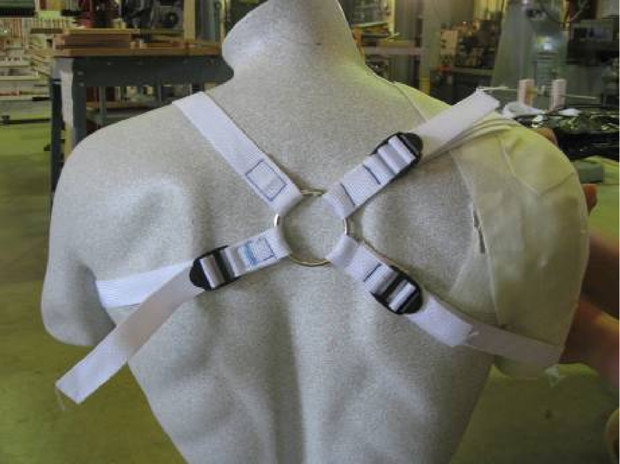 Figure 2: Final Design of Harness. Setup of harness with cable attachments. (Click for larger view)
 A prototype was constructed in order to gain feedback on the preliminary design. The cable and harness system was designed to operate the prosthesis using an amputee’s body movement. The two cables were used to move and lock the prosthesis and the harness was used for suspension and control. A carabiner attached each cable to the harness. The harness was positioned in a figure eight over the amputee’s shoulders (Figure 2). The cable for elbow motion was attached to the terminal device, and ran through guides outside the forearm, around the humerus, to the back before being attached to the harness. The locking cable was run up the front of the humerus and attached to the harness at the front of the shoulder.
 Figure 3: Final Design of Lock Mechanism. Setup of components used for locking mechanism. Key parts include the cam, wrench, cable, and locking slider. (note: in final design, toothed gear is replaced by torsion spring) (Click for larger view)
 The locking mechanism was composed of a cylindrical shaft, an elliptical cam, a torsion spring, a wrench arm and a tension spring, and it was setup as shown in Figure 3 (note: the torsion spring is replaced in the figure by the toothed gear). The cable attached to the wrench arm, and is pulled by the amputee’s body motion. This will generate a friction between the torsion spring and shaft that causes it to tighten when rotated one direction but loosen in the other. Therefore, the tightened wrench will rotate the shaft and cam assembly. The wrench is rotated back into the original position by a tension spring. The torsion spring loosens and does not engage the shaft and cam. In this way, the shaft is rotated 90 degrees in the same direction every time, locking and unlocking the elbow. The entire locking mechanism is positioned behind the sliding pin in the International Red Cross arm. A knob is connected to the locking pin and protrudes out the top of the forearm to allow for manual locking and unlocking when necessary.
 Figure 4: Results of cable tension versus load test. Two types of housing were tested at two different guide positions on the forearm. (Click for larger view)
 In order to be certain of our preliminary design calculations, a series of tests were designed. These tests included: tensile force in elbow motion cable versus load being lifted; elbow angular deflection versus cable pull length; tensile force in locking cable versus attachment position to wrench arm in locking mechanism. According to the report by Bertels, a typical amputee can generate 4in pull with 50lb force (2). The test results for cable tensions and cable pull lengths (Figures 4, 5, 6) were in the acceptable range, thus validating the design specifications.
 Figure 5: Results of cable pull length versus arm angle test. (Click for larger view)
 Tests were also performed to select final materials, cable positioning and locking assembly orientation. Based on these results, black rubber was chosen for housing material, steel was chosen for most parts of the locking mechanism, and cables were positioned and attached to minimize tension. For cable and harness materials, inexpensive bicycle brake cables and nylon straps were used since they can easily be found in developing countries.
Final Design
 Figure 6: Results of cable tension versus wrench arm length test in the lock and unlock modes. (Click for larger view)
 Based on the test results, minor adjustments were made in order to optimize the functionality of the final design. Detailed engineering analysis was performed under static and variable loading in order to properly size components and calculate design factors to analyze the safety/ likelihood of failure. This detailed analysis can be seen in the comprehensive design report submitted to the University of Arkansas
(3). Based on the calculations, the design specifications were selected and can be seen in Table 2.
The modifications allow for the prosthesis to be operated completely independent of the amputees other arm. The elbow motion cable is pulled when both shoulder blades are stretched away from the backbone. This motion applies tension and raises the forearm. As the shoulder blades are relaxed, the cable is relieved of tension and the forearm is lowered. The locking cable is pulled by dropping the shoulder, which actuates the lock into one of seven lock positions.
| PART | Diameter(d)/Breadth(b) (in) | Length (in) | Thickness (in) | Material |
|---|---|---|---|---|
| 1) LOCKING BAR | ||||
Horizontal Part of Slider Bar |
d=0.25 | 1.5 | NA | AISI 1015 steel |
Vertical Part of Slider Bar |
d=0.1 | 1.5 | NA | AISI 1015 steel |
Top Manual Knob |
b=0.1 | 0.5 | 0.1 | AISI 1015 steel |
| 2) CAM : Elliptical shape | ||||
Major Axis |
d=1.4 | NA | 0.1 | AISI 1020 steel |
Minor Axis |
d=0.2 | NA | 0.1 | AISI 1020 steel |
3) SHAFT (solid) |
d=0.2 | 2.75 | NA | AISI 1020 steel PVC Aluminum 2024-0 |
| 4) WRENCH PIECE | ||||
Circular part |
d=0.6 | NA | 0.1 | AISI 1020 steel |
Wrench Arm |
b=1.5 | 0.7 | 0.1 | AISI 1020 steel |
5) SPRING |
Type | Free length (in) | Spring rate (lb/in) | Material |
Spring 1 |
Tension | ~ 1 | NA | Aluminum/steel |
Spring 2 |
Compression | ~1.5 | ~ 0.04 | Music wire (steel) |
The goal of this design was to make adjustments to the International Red Cross above-elbow prosthesis that will give the amputee more functions provided by a normal arm. Through the use of a dual cable system, one cable to move the arm and one cable to lock/ unlock it, the amputee is able to operate the International Red Cross prosthesis independently of the other arm. Not having to depend on the amputees other arm allows the amputee to gain function closer to that of two normal arms, and be able to use them simultaneously. The changes made to the IRC arm significantly enhance performance, while maintaining affordability and appropriateness for use in developing countries. These developments of prosthesis design can help to provide needy amputees with a more-functional arm, thus restoring their chance for a livelihood, and improving their quality of life.
References
- Sitek, A. et al. (2004). Development of an Inexpensive Upper-Extremity Prosthesis for Use in Developing Countries. Journal of Prosthetics and Orthotics. 16 (3). 94-102.
- Bertels, T. (2001). Functions of the body harness for upper extremity prostheses. Otto Bock HealthCare GmbH (Duderstadt). 1-5.
- Bhise, N., Carlisle, R., Huber, S., Richardson, W. (2007). Design of an Above Elbow Body Powered Prosthesis for Developing Countries. Comprehensive design report submitted for BENG 4822 (Senior Design In Biological Engineering) at the University of Arkansas, May 3, 2007. Available from: Thomas A. Costello, Associate Professor, Biological Engineering, University of Arkansas <tac@uark.edu>.
Primary Author
Nupura Bhise- 203 Engineering Hall, University of Arkansas, Fayetteville, AR 72701, 479-575-2351