Adaptable Prosthetic Foot & Ankle Mechanism for Sloped Walking
Ryan Williams, BS
ABSTRACT
A prosthetic foot & ankle mechanism was designed to automatically adapt to the walking surface on every step in order to alleviate the challenge of walking on uneven terrain for people with below-knee amputations. The purely mechanical device aligns to the walking surface and utilizes stiffness control in order to provide proper support once it has “found” the surface. The mechanism was tested on three subjects with unilateral, transtibial amputations walking on level surfaces and on ramps. Preliminary results indicate that the mechanism provides more ankle motion than the usual prostheses used by the subjects while walking on slopes. Further analysis of the acquired data is needed to verify that the mechanism is properly adapting and simulating the behavior of the anatomical ankle.
Keywords:
prosthetic foot, prosthetic ankle, adaptable, smart prostheses, slope walking
BACKGROUND
The need to walk on sloped surfaces is a demand that most humans face everyday. While walking on slopes does not pose a great challenge for able-bodied walkers, people with amputations may find it more difficult due, in part, to the high stiffness of prosthetic feet (1-4). Most prostheses do not have an ankle joint, forcing the foot to deform in a way that compensates for the missing ankle (5). There is a need for new designs of ‘smart’ prostheses that can automatically adapt to various walking surfaces (5). In the 1960’s Hans Mauch developed a hydraulic foot & ankle mechanism that adjusted its alignment according to the slope of the walking surface. It did a good job at simulating the behavior of the anatomical ankle and was well-liked by users for walking up and down slopes (6). The foot & ankle mechanism would eventually fail due to leakage of hydraulic fluid, but it was very successful before the leaking occurred. Its limited success is evidence that an automatically adapting ‘smart’ ankle would greatly aid walking on slopes.
At low to normal walking speeds, the able-bodied ankle joint has behavior that can closely be mimicked using passive devices (7). These characteristics change at important points throughout the gait cycle: the stiffness of the ankle is low during early stance phase, but after foot flat the stiffness increases and remains high until the initial contact of the contralateral foot (when unloading begins). Therefore, as opposed to Mauch’s design which relied on variable damping concepts, the mechanism designed in this investigation utilizes stiffness control to provide the proper amount of stiffness throughout the gait cycle. Stiffness is increased once foot flat is reached and then reduced directly after toe off. The “set-point” of the mechanism gets reset on every step in order to reach the proper alignment for the walking surface. There are currently no known commercially available prostheses which have this capability. (The Proprio Foot™ by Ossur® comes close, but it requires a few steps on a ramp before it will “learn” the surface that it is walking on and make the proper adjustments.)
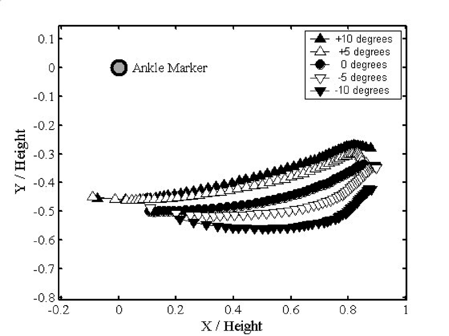
It was hypothesized that the roll-over shapes (Figure 1) of the mechanism designed in this investigation would be similar to those produced by the physiologic knee-ankle-foot complex; in particular, the mechanism would shift into a more dorsiflexed position when walking uphill and into a more plantar flexed position for walking downhill (Figure 2) (5). By adapting to the walking surface, the mechanism would minimize the challenge of walking on uneven terrain.
DESIGN
Project Goal Statement
The overall goal for this project was to design, develop, and test a prosthetic foot & ankle mechanism for a person with a unilateral, transtibial amputation. The primary specifications for the mechanism were that it must be capable of automatically adapting on every step to the walking surface and that it not require any active control.
Design Description
A prototype foot & ankle mechanism (Figures 3, Figure 4, Figure 5) capable of automatic adaptation was developed and tested. The prototype created is purely mechanical and therefore involves only passive control. A CAD model of the prototype (constructed using SolidWorks 3D CAD Software (SolidWorks Corporation, Concord, MA)) shows most of the components from the prototype (see Figure 6, Figure 7, Figure 8 for pictures of the model, names of each part, and a description of how the parts interact).
The mechanism utilizes the user’s body weight to change the stiffness mode of the ankle joint. As the user steps onto the mechanism, the rotation of the Arms is resisted only by the Soft Bumpers (the mechanism is in the “low-stiffness” mode) and the Foot Plate is easily able to reach foot flat. The user’s weight shifts onto the mechanism and the Upper Housing presses down onto the Compression Springs. As the Upper Housing slides down along the Shoulder Bolts it pushes the Link into the Cam, causing the Cam to rotate down and jam into the Base (see Figure 9). At this point, as the Arms try to rotate forward (ankle dorsiflexion) the Base is resisted by the anterior Stiff Bumper (the mechanism is now in the “high-stiffness” mode). Towards the end of stance phase the user’s weight comes off of the mechanism and the Compression Springs push the Upper Housing away from the Arms. This action pulls upward on the Link, rotating the Cam off of the Base (see Figure 10). The rotation of the Arms is once again only resisted by the Soft Bumpers, which force the Arms back into a neutral alignment (the mechanism is back in the “low-stiffness” mode) to prepare the mechanism for the next step. The “set-point,” at which the mechanism changes stiffness modes, automatically gets reset on every step, thus allowing for the proper alignment of the mechanism depending on the slope of the walking surface.
METHODS
Subject Information
Three subjects with unilateral, transtibial amputations were recruited and signed IRB approved consent forms to participate in the experiment. All were declared good ambulators by a certified prosthetist (CP).
Data Acquisition
Testing took place at the VA Chicago Motion Analysis Research Laboratory (VACMARL) which contains eight Digital RealTime motion analysis cameras (Motion Analysis Corporation™ [MAC], Santa Rosa, CA) and 6 force platforms (AMTI, Watertown,MA).
Test Protocol
Subjects were asked to walk with their standard prostheses at their normal self-selected speed on a level surface, up and down a ramp with a 5 degree inclination, and up and down a ramp with a 10 degree inclination (8) (Figure 11, Figure 12). A CP then fit the subjects with the experimental foot & ankle mechanism and they were again asked to walk under the same conditions. Standard kinetic and kinematic measurements of gait were acquired. After the subject completed the study, he/she was asked for a subjective evaluation of the foot & ankle mechanism.
Data Analysis
The marker data sets were loaded into EvA RealTime (MAC™) and were joined using cubic spline interpolation techniques and smoothed using a second order bi-directional filter with an effective cutoff frequency of 6 Hertz. The filtered data were then processed using OrthoTrak (MAC™), which calculates temporal-spatial gait data, and joint angles and moments.
RESULTS
Preliminary results have been obtained for the first two subjects that were tested. Both subjects verified that walking on ramps with their usual prostheses was a significant challenge, and that the foot & ankle mechanism that has been developed offers distinct advantages over other prosthetic feet they have used while walking on ramps. Unsolicited, one of the subjects noted “this is a good ramp foot.” A preliminary look at the data obtained indicates that, as compared to the subjects’ usual prostheses, the mechanism provides additional ankle motion and provides equal or greater energy return during a gait cycle.
DISCUSSION
Further analysis of the acquired data is needed before conclusions about the mechanism’s success can be determined. Specifically, we will analyze the roll-over shapes to confirm that the mechanism is indeed adapting to the walking surface and is effectively mimicking the anatomical foot & ankle complex.
REFERENCES
- Edelstein, J. E. (1988). Prosthetic feet. State of the Art. Phys Ther, 68(12), 1874-81.
- Gailey, R. S. a. C. R. C. (2004). Physical Therapy. In D. G. Smith, Michael, J.W. & Bowker, J.H. (Ed.), Atlas of Amputations and Limb Deficiencies: Surgical, Prosthetic, and Rehabilitation Principles (Vol. 3, pp. 589-619). Rosemont: American Academy of Orthopaedic Surgeons.
- James, K. B., & R. B. Stein. (1986). Improved ankle-foot system for above-knee amputees. Am J Phys Med, 65(6), 301-14.
- Singer, E., G. Ishai, & E. Kimmel. (1995). Parameter estimation for a prosthetic ankle. Ann Biomed Eng, 23(5), 691-6.
- Hansen, A. H. (2002). Roll-over characteristics of human walking with applications for artifical limbs. Unpublished PhD Dissertation, Northwestern University.
- Sowell, T. T. (1981). A preliminary clinical evaluation of the Mauch hydraulic foot-ankle system. Prosthet Orthot Int, 5(2), 87-91.
- Hansen, A. H., D. S. Childress, S. C. Miff, S. A. Gard, & K. P. Mesplay. (2004). The human ankle during walking: implications for design of biomimetic ankle prostheses. J Biomech, 37(10), 1467-74.
- Hansen, A. H., D. S. Childress, & S. C. Miff. (2004). Roll-over characteristics of human walking on inclined surfaces. Hum Mov Sci, 23(6), 807-21.
ACKNOWLEDGEMENTS
The author would like to acknowledge the use of the VA Chicago Motion Analysis Research Laboratory of the VA Health Care System, Chicago, IL. This work is funded by the National Institute on Disability and Rehabilitation Research of the US Department of Education under Grant No. H133E030030. The author would also like to thank Drs. Steven A. Gard and Andrew H. Hansen for all of their help.
AUTHOR CONTACT INFORMATION
NUPRL & RERP; 345 E. Superior St., RIC 1441; Chicago, IL 60611
(312) 238-6500