Laptrays with Elevating Mounts for Speech Generating Devices
Mark I. Bresler, MBME, PE, Charles Crist, John B. Storm, M.F.A.
Squier Assistive Technology Center - Woods Services
Langhorne, PA 19047
ABSTRACT
Two power base users are starting to use Speech Generating Devices. In order to not restrict their vision, two laptrays with recessed, flip down mounts were constructed. One lap tray is for a nonverbal 36-year-old young man with severe cerebral palsy. HW does not have control of any extremity and uses head control to operate his power base. Due to his lack of voluntary movement, power lap tray movement was pursued. The second lap tray is for a 13 year old student who lost use of her legs and right arm due to brain injury in a bike accident. PD has good use and fine motor control with her left arm.
KEYWORDS
AAC, SGD, Mobility Base, Mount
BACKGROUND
Current communicator mounts do not allow switch users such as HW to independently move their devices out of the way when not in use. Individuals such as PD with limited use of one hand also find it hard to manipulate swing away mounts. Additionally, staff had difficulty keeping the mounting block from slipping on the round power base tubing. For these reasons, alternate laptray mounting was explored. Both users had room between the laptrays and their thighs to accommodate storage of the devices.
Design goals for HW included:
- Reduce visibility restrictions
- Using existing power base controls
- Keep laptray power separate from power base
- HW is using a Prentke Romich Company Deltalker
Design goals for PD included:
- Reduce visibility restrictions
- Making the communicator available quickly (for example hallway conversations)
- Allow the lap tray surface to be used for writing and drawing
- Allow her to manipulate laptray parts independently
- PD is using a Prentke Romich Company SpringBoard II
METHODOLOGY
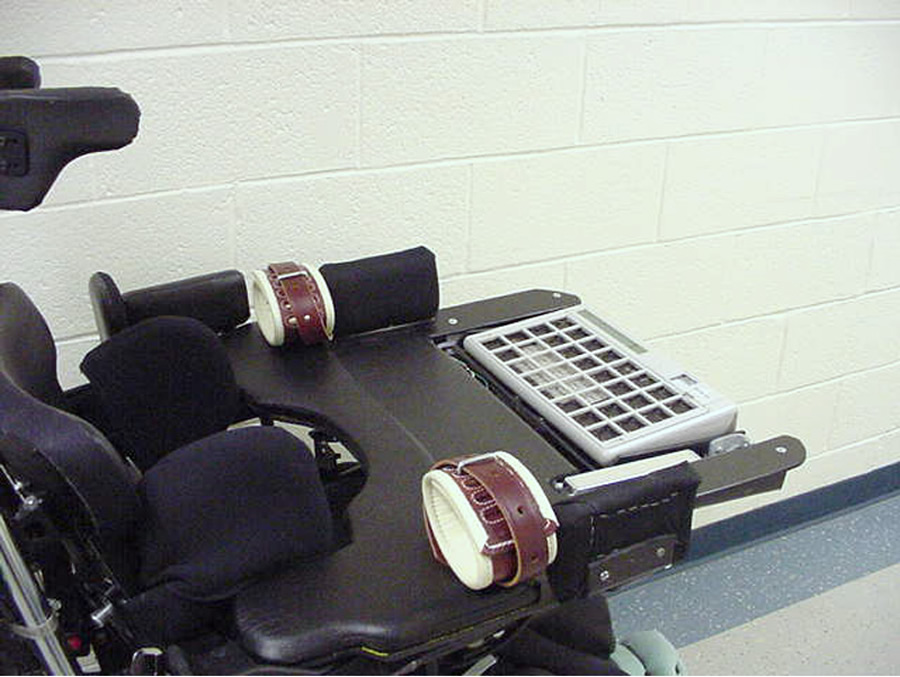
Photo 1: Power Laptray ( communicator down) (Click for larger view)
For both laptrays, a spring loaded gate hinge was used to reduce the effort needed to move the communicators into position. The power elevation mechanism went through several iterations. The first design utilized servomechanisms typically used in remote control models. A microprocessor was programmed to supply the control pulses needed to move the servomechanisms between two preset angles. The servomechanisms worked fine without a load, however when asked to move the communicator, the friction was enough that the servo mechanisms never exactly matched the commanded angle and constantly spent power trying to reach the commanded angle. A larger servomechanism was substituted with the same results. While digital servomechanisms could have been used with adjustments to the dead band to eliminate the hunting for final angle, other approaches were investigated. Linear actuators were found with built in limit switches, and by adjusting the attachment points to the mount, the desired 0° to 60° movement was established. The first control circuit for the linear actuators used two timers, each giving a five second pulse when triggered, one for up and one for down to drive control relays. The final circuitry substituted an integrated circuit motor drive for the relays, reducing power consumption. While the current circuitry does not allow adjustable viewing angle, this could be developed if desired.
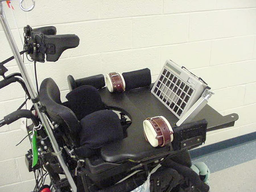
Photo 2: Power Laptray (communicator up) (Click for larger view)
HW is using a three sensor ASL head array to operate the Invacare Mark V electronics on his power base with power tilt. A communication module was added which allows his head array signals to operate his communicator, computer, and television. The ECU output 1 is being used for the communicator. A right activation elevates the communicator and is the scanning input, a left activation lowers the communicator.
ECU 2 will operate the computer and television. The communicator and programming chosen for HW is further described in a paper submitted for RESNA 2009 (1)
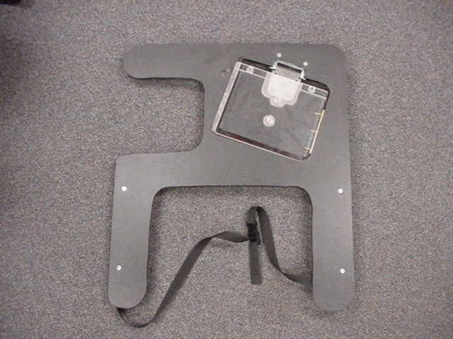
Photo 3: Manual Laptray (communicator down) (Click for larger view)
HW found he has better control with his arms restrained. With his, and his family’s consent, and approval from medical and management personnel, arms straps were incorporated into his lap tray.
To raise her communicator into operating position, PD lifts a Velcro loop on the Plexiglas cover, which is hinged on the right side. Next she guides the communicator into position, and finally lowers the Plexiglas cover so the area can be used as a work surface. To lower the communicator, she reverses the process.
The cutout on the left side of the manual laptray provides room for the swing away joystick control.
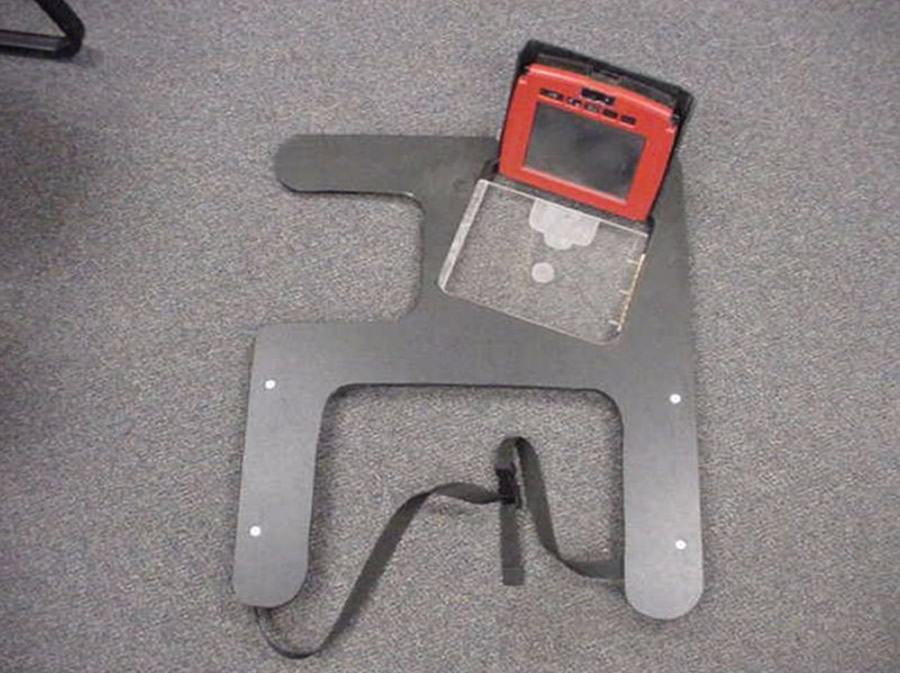
Photo 4: Manual Laptray (communicator up) (Click for larger view)
While both devices happen to be Prentke Romich Company communicators, these mounting techniques could be used with other company’s devices. Indeed it is not limited to Speech Generating Devices, Personal Digital Assistants, and tablet PC’s could also be mounted in this fashion. This technique can also be used with low-tech devices such as a slant board for reading or writing.
RESULTS
The manual laptray has been used by PD in her educational setting for the last week, once residential staff is trained in its care and use it is expected to be with her around-the-clock on a daily basis.
Continued use of the power laptray is waiting for repair and return of HW’s power base.
DISCUSSION
The laptrays described here are prototypes, further refinement will take several forms, these will include:
- Making the laptrays stiffer and lighter
- Optimizing the power laptray for reliability, battery life and battery weight
- Investigate methods to reduce electrical connectors.
REFERENCES
(1) Bresler, MI, “Accommodating Personal Choice with Speech Output Communication Systems.” Submitted for RESNA 2009
ACKNOWLEDGEMENTS
The author wishes to thank the following people for their assistance on this paper:
Joe Campbell: Senior Occupational Therapist, and Penny Evans-Kelly: Educational Services Administrator, for manuscript review.
Parts used in these laptrays were purchased with funds from the Squier Assistive Technology Fund.
Author Contact Information:
Mark I. Bresler, MBME, PE, Assistive Technology Specialist, Woods Services, PO Box 36, Langhorne, PA 19047
(215) 750-4112 voice, (215) 750-2987 fax, mbresler@woods.org , www.woods.org